Week 4 Challenge
1.Calculate dead load in design report based on IS code and apply dead load on the model
- Finishes of 50mm
- Slab as per design
- Brickwall 150mm thickness
- Roofing load based on purlin size
- Ceiling loading 0f 0.3KN per sq m
Ans)
Aim: To calculate dead load in design report based on IS code and apply dead load on the model.
Tools Required:
->Manage Properties
->Slabs
->Properties tab
->Load
->Load cases
->Dead load
->Imposed load
->Area
->Full UDL
->Line
->Validation
Calculations:
DEAD LOAD :
Slab load = Model slab in software.
Finishes loading (50THK) = 0.05m x 24 KN/m^3 = 1.2 KN/m^2.
Brick wall with cement plaster thickness = 150mm.
Unit weight = 20 KN/m^3
Floor height (GF to FF) = 5.2 m
Brick wall loading = 15.6 KN/m
Floor height (FF to Roof) = 6.8 m
Brick wall loading = 20.4 KN/m
Roof loading = 1.5 KN/m^2
Procedure:
- Firstly, open the file which was created earlier.
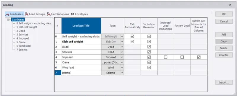
- Go to load tab and select load cases option under that, Load cases dialog box appears.
- Create new load such as crane, seismic and wind load to the list of predefined loads.
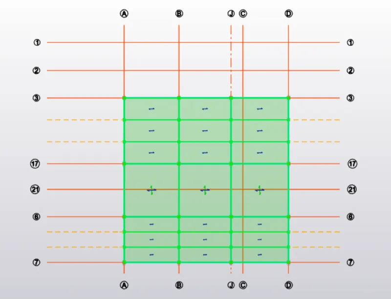
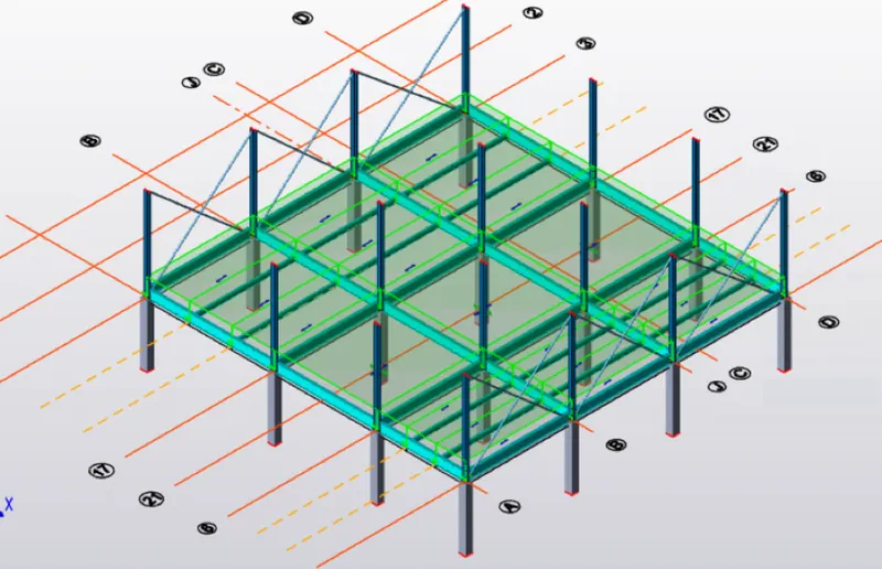
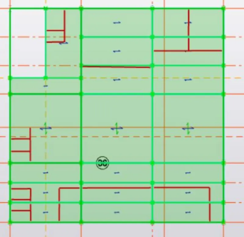
- Now we have to create slabs for all the layers required.
- Based upon the dimension of the adjacent beams we have to select one way or two way slabs, that is to select the two way option when the ration between the values is less than 2 else select the one way slab itself.
- Also while adding the slab do create slab S1 with one way and S2 with two way the major changes among the S1 and S2 is nothing but this itself.
- Now the parameters are select the bar type 10, bar spacing as 150mm, over depth as 200mm and the grade as M25.
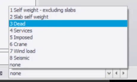
- Now at the bottom of our workspace we find dead load option in the drop up dialog box.
- Under load tab we have to select area and give the value of 1.2KN/m square, and select all the slabs.
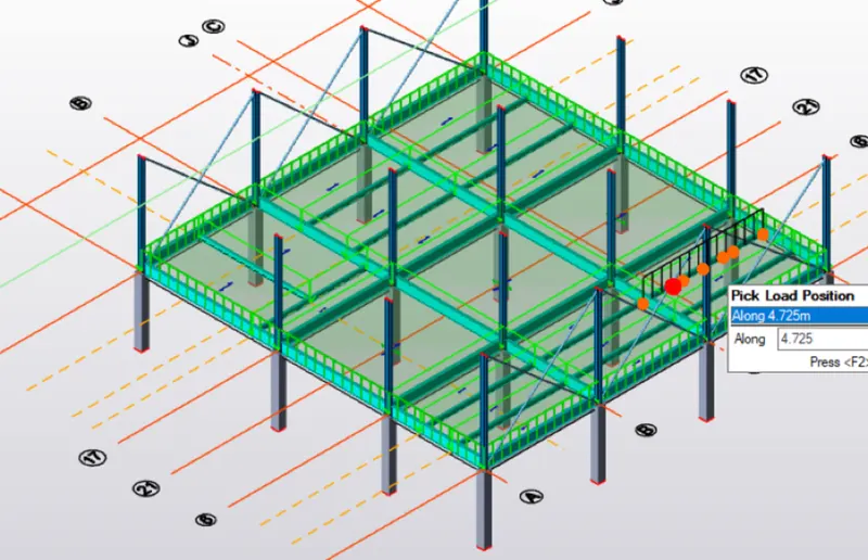
- Now we have to select Full UDL and apply the dead load to all the beams.
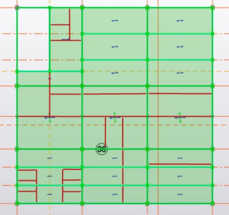
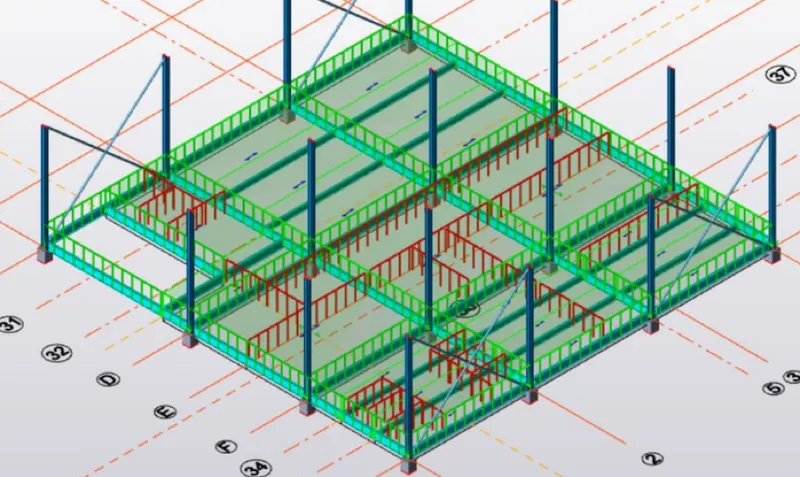
- Now select Line tool under load tab and draw the walls load in all the required floors.
- Do not forget to validate your model every now and then as to check your errors and correct them.
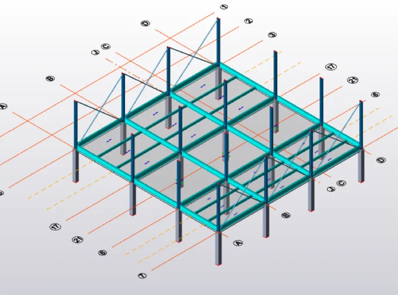
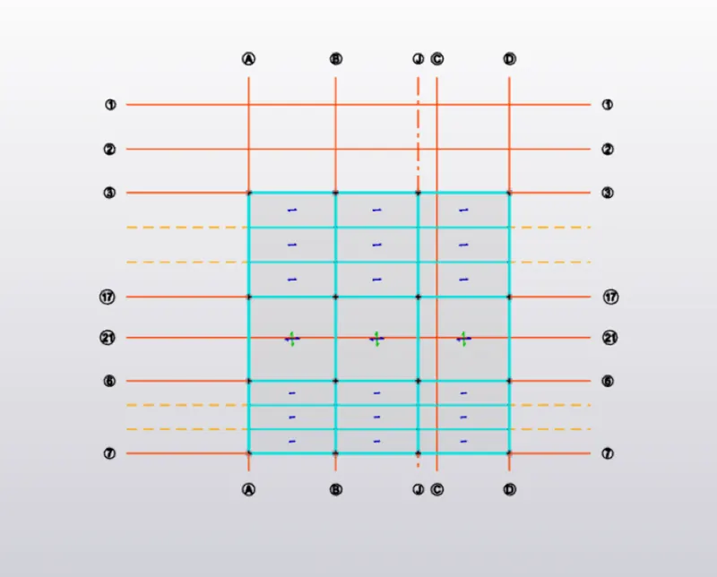
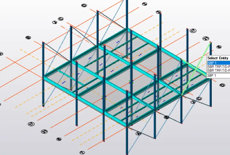
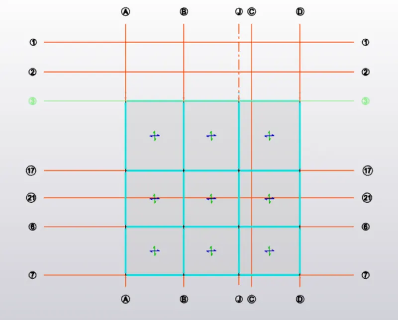
Result:
Hence by following the above procedure we will be able to provide the dead loads to the slabs and beams for structure.
2.Calculate live load in design report based on IS code and apply live load on the model
- Assume the loading based on IS 875
- Roof loading
- Consider equipment loading as 5KN per sq m
Ans)
Aim:To calculate live load in design report based on IS code and apply live load on the model.
Tools Required:
->Load
->Load cases
->Dead load
->Area.
Procedure:
- Firstly, open the file in which the dead loads were added.
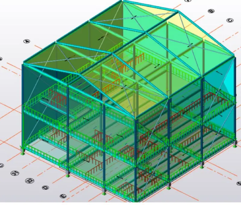
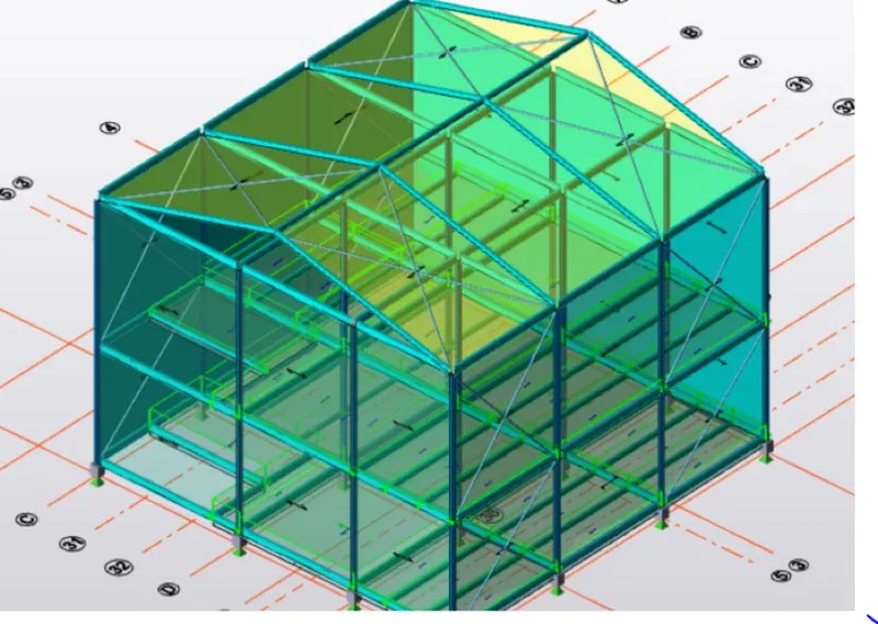
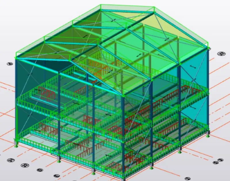
- Now at the bottom of our workspace we find imposed load option in the drop up dialog box.
- Now we can provide live loads to the structure by selecting the load and assigning the value for it according to the IS Code.
- Click on loads icon and select area option under that.
- The live loads for the structure can be obtained from the IS building standard codes.
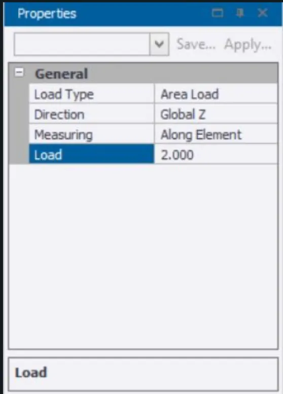
- Now under the property dialog box enter the required load for different room.
Store room = 5 KN/m^2
Office = 3 KN/m^2
Rest room = 2 KN/m^2
Toilets = 2 KN/m^2
Pantry = 3 KN/m^2
Corridor = 4 KN/m^2
Equipment room = 10 KN/m^2
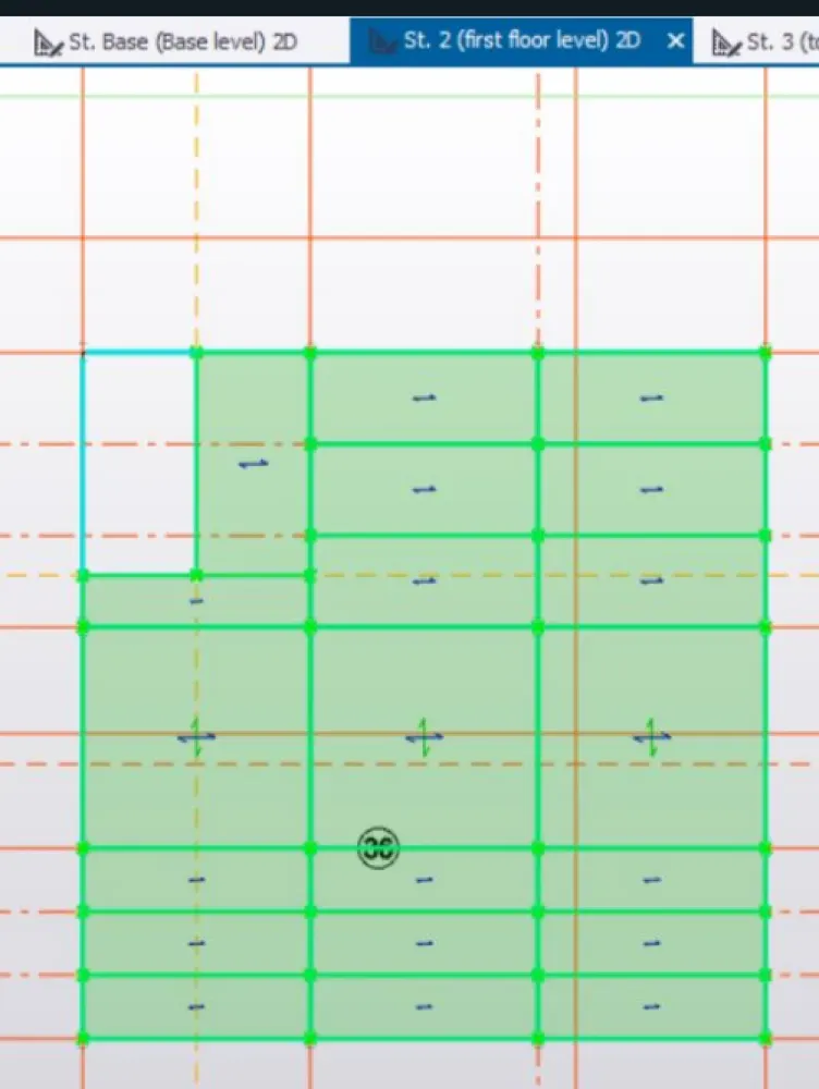
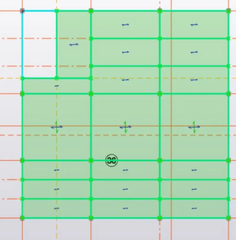
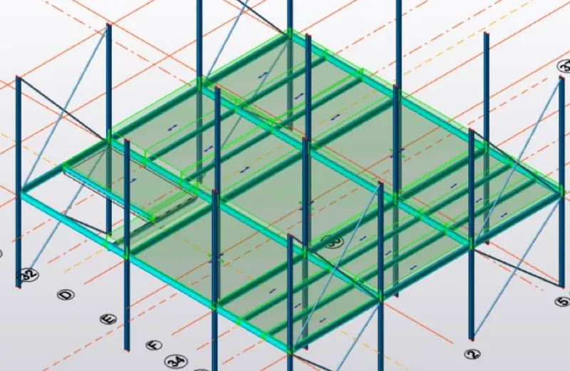
- Now set the loads with different values and apply them by clicking on the respective slabs.
- Now repeat the same process for all the remaining levels that is for the first and to top of the roof level.
- Do not forget to validate your model every now and then as to check your errors and correct them.
Result:
Hence by following the above procedure we can apply live loads to the structure and calculate.
3.Generate a calculation for 5T crane loading based on following inputs
- Centre to Centre of wheel = 10m
- Weight of crab = 40 KN
- Number of wheels = 4
- Wheel base = 2m
Ans)
Aim: To generate a calculation for 5T crane loading based on following inputs.
Calculation:
Max wheel load
Maximum concentrated load on crane = 50 + 10 = 60 KN.
Self-weight of crane will act as uniformly distributed load of intensity
=40 / 10 = 4 KN/m.
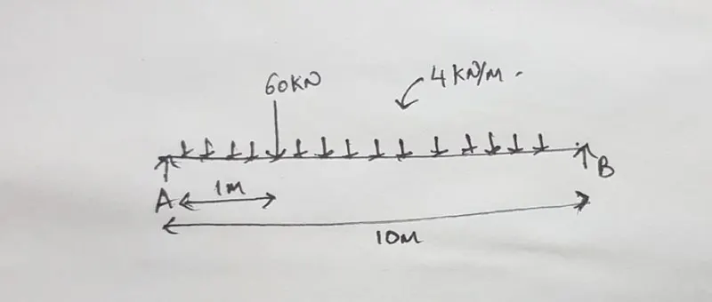
Taking moment about B :
Ra x 10 – (60 x 9)- (4 x 5 x 10) = 0
10 Ra = 740.
Ra = 74 KN.
Rb x 10 –(60 x 1)-(4 x 10 x 5) = 0
10 Rb = 260
Rb = 26 KN.
Ra + Rb = 100 KN.
The reaction from the crane girder is distributed equally on two wheels at the end of the crane girder.
Maximum wheel load on each of the crane wheel = 74 / 2 = 37KN.
MAXIMUM BENDING MOMENT :
Assume self-weight of the gantry girder as 1.5 KN/m
Total dead load = ( Self-weight of rail + self-weight of gantry girder ) 300 + 1500 = 1800 N/m
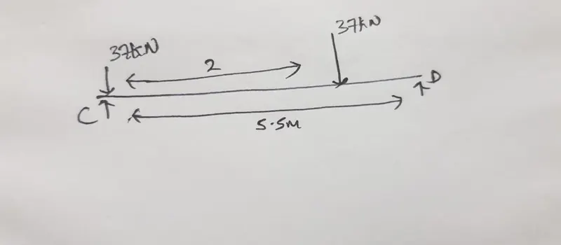
Taking moment about D
Rc x 5.5 –(37 x 4.25)- (37 x 2.25) = 0
Rc x 5.5 = 240.5
Rc = 240.5 / 5.5
Rc = 43.72 KN.
Rd x 5.5 – (37 x 1.25)- (37 x 3.25) = 0
Rd x 5.5 = 166.5
Rd = 166.5 / 5.5
Rd = 30.27 KN.
Bending moment under wheel due to live load = Rd x 2
= 30.27 x 2
= 60.54 KN.
Bending moment due to impact = 0.10 x 60.54 ( 10 % increase due to MOT)
= 6.054 KNm
Total bending moment due to live load and impact load = 60.54 + 6.054
= 66.594 KNm.
Bending moment due to dead load = W x l x l / 2
= 1.8 x 5.5 x 5.5 / 2 = 27.22 KNm
Maximum bending moment = 66.594 + 27.22
= 93.814 KNm.
MAXIMUM SHEAR FORCE :
For maximum shear force, one of
Rc x 5.5 –(37 x 5.5)-(37 x 2.5) = 0
Rc = 9.25 + 20.35 / 5.5
Rc = 5.381 KN
The maximum shear force due to wheel load = 5.31 KN
LATERAL FORCES :
Lateral forces traverse to rails = 5% of the weight of crab and weight lifted
= 0.05 ( 40 + 10 )
= 2.5
Lateral forces on each side wheel F1 = 2.5 / 2 = 1.25 KN
Maximum horizontal reaction due to the lateral force by proportion at C
= Lateral force x reaction at C due to vertical load / maximum wheel load due to vertical load
= 1.25 x ( 43.72 / 37) = 1.44 KN
At D
2.5 – 1.44 = 1.06 KN
Bending moment due to lateral load by proportion
= (1.25 / 37) x 5.31
= 0.179 KNm.
Result:
Hence by following the above steps of procedure we could generate the calaculation for the 5T crane loading.