Basic pre-processing operations on a bracket model using Hypermesh
PRE-PROCESSING A BRACKET MODEL
AIM:
To preprocess the given bracket model by extracting it for mid-surface and then meshing using shell elements and finally creating 1D elements representing the cross-section of a Bar, Beam, and Rod elements.
PROCEDURE:
1. Mid-surface extraction
- Import the .iges CAD geometry using the import - Geometry command
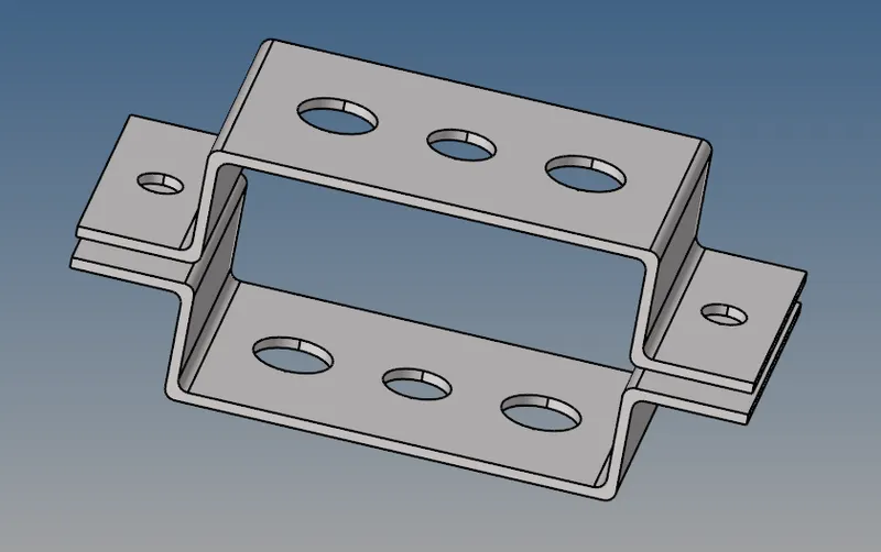
Fig: CAD model
- Since there are four methods to extract the mid-surface of the solid component, we have to chose the one that gives a more appropriate result during the meshing.
- The extraction method can be selected by: Midsurface - extraction option - (select the method)
- (Optional) The entire solid model is copied to compare each method and its mesh result using the Translate command
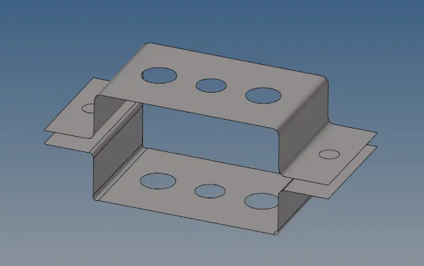
Fig: Mid using Offset+plane+sweep
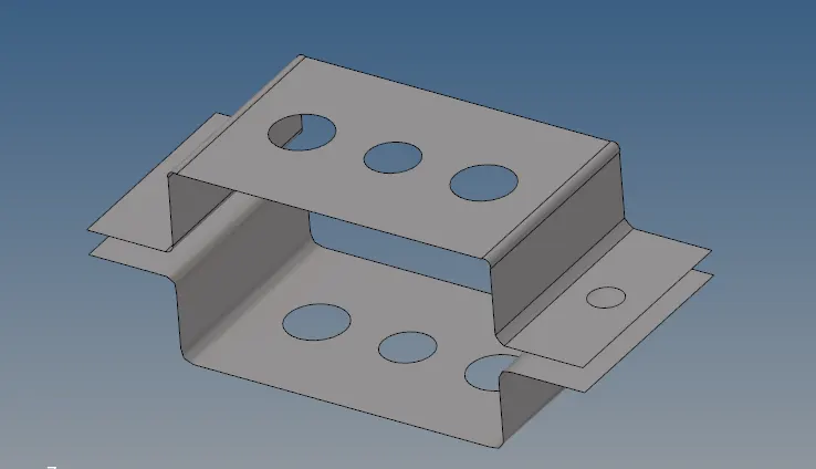
Fig: Mid using offset planes
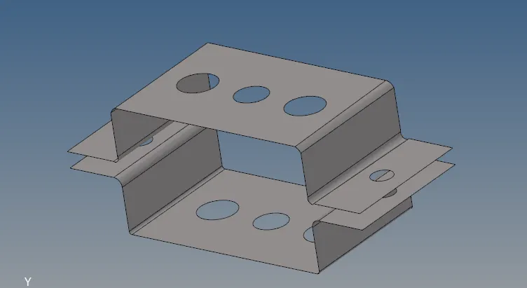
Fig:Mid using offset
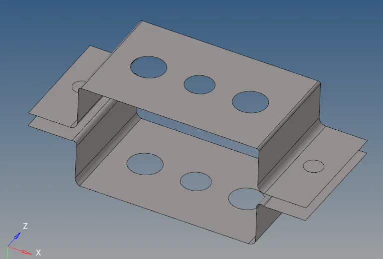
Fig: Mid using skin offset
Of the four methods, the offset+planes+sweeps method gave the worst result during the 2D meshing since the fillets are not sperated by any cons(lines) from the flat surface. The other three methods gave a more appropriate construction of the model. However, the skin offset method is selected.
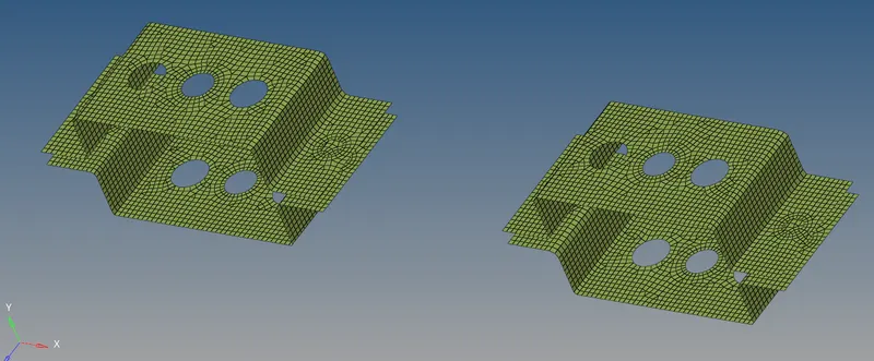
Fig: Shell meshing of all mid components
- After slecting the preferred mid component, create a new component from the model tree and assign it to each mid-surface component from the Tools command
- To assign the mid surf to a component: Tools - Organize - (select surf) - select dest comp - move
2. Shell Meshing
- Before meshing the component, the washers are created around the holes using the quick edit - washer split - offset
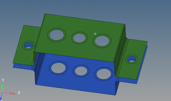
Fig: Washer split
- To generate shell elements over the entire surface: 2D - automesh - size = 5 - mixed element type - mesh
- There should be even number of elements at the holes and the no of elements present at both the washer and hole must be the same.
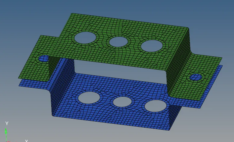
Fig: Meshed surface
3. Assign property card
- Before assigning a property card for create material card for the components . The card image for the steel material is MAT1 in Optistruct.
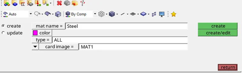
Fig: Material property card
- Then two property cards are created for the two mid surfaces. A single card (like PSHELL) can be created for both the mid component if they share the same identical property. However in our case, each mid has a different thickness thereby each required different card specifing its respective thickness.
- While creating each property card, the material card is assigned.
- To make use of the material card, the required material quantities like youngs modulus, Poissons ratio, etc. must be initialized from the model tree in the Materials sectioon.
- The thickness for each the bracket component can then be assigned in the property window.
4. Creating rigid elements
Rigid elements
Rigid elements like RBE2 and RBE3 are elements that offer a variant of the multi-point constraint feature where a set of nodes are dependent /independent to each other or a set of different nodes.
The difference between a RBE2 and RBE3 element would be that an RBE2 element would impose a rigid connection whereas using an RBE3 element would impose a distributed connection. Moreover, the RBE2 element also functions as a rigid element such that it imparts stiffness onto the constrained nodes. However in the RBE3 element, the motion of the dependent single node is determined by averaging the motion of all the independent nodes (i.e there is relative displacement) and moreover the nodes and the entire element in general do not contribute any stiffness in that area of the model.
Fig: Rigid elements (RBE2 and RBE3)
In Hypermesh to create a rigid RBE2 element:
1D - rigids - single/multi nodes - select dependent nodes - constraint the dof - create
NOTE: The master node i.e independent node will be autoatically calculated by HM based on the slave nodes
In this case, the RBE2 element created at the "a" "d" and "e" section of both the top and bottom brackets and are constrained only in the translational direction (i.e dof 1,2 and 3) and all the rotational dof's are kept unchecked.
Similarly to impose a rigid RBE3 connection:
1D - rbe3 - select independent nodes - constraint the dof - create
NOTE: The dependent node will be autoatically calculated by HM based on the other set of independent nodes
In this case, the RBE3 element created at the "b" and "c" section of both the top and bottom brackets and are constrained at all dof in case of "b" and only at x and y dofs (i.e translational and rotational at x,y) in case of "c".
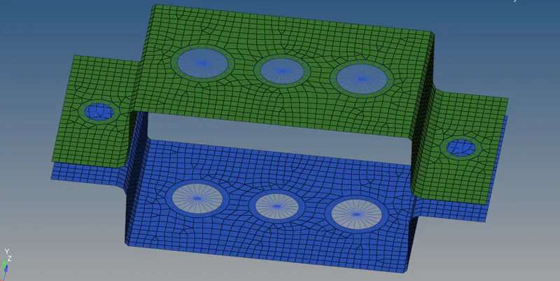
Fig: rigid elements
NOTE: If any property change has to be made on any rigid element, the update tab under rigids/rbe3 can be used.
5. Hyperbeams
Hyperbeams can be used to create actual shape and cross-section of beam, bar or rods that are pre-defined and created using 1D elements.
Prior to assigning the CS for each element the 1D representation of that element has to be modeled.
a: Rod
To create a rod 1D element at section a:
1D - rod - create - select 2 nodes - elem type = CROD - assign a new property - create
A new property must be created and assigned a PROD card and the preferred material. For the beamsec in the property card a new hyperbeam is created using:
1D - Hyperbeam - standard - hyperbeam - thinwalled box - specify dimensions.
This new CS can be assigned to the rod property and updated for the rod element.
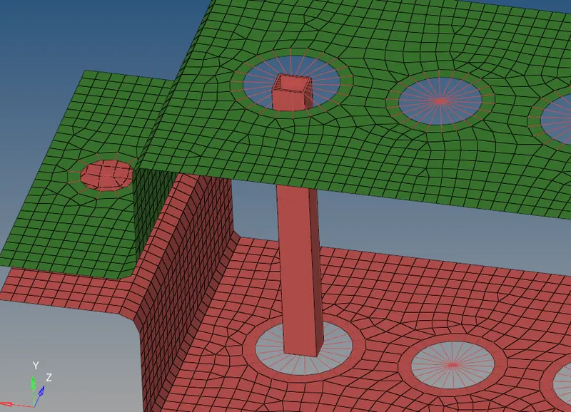
Fig: Rod element
b: Beam
Similarly to create a CBEAM:
1D - bars - bar2 - (select nodes) - elem type = CBEAM - (select property) - create
A new hyperbeam element w a beam cross-section with an I-section.
similarly a new property is assigned to the 1D element (as shown below)
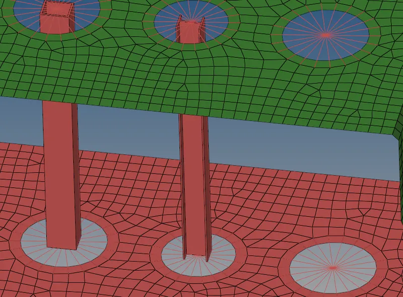
Fig: Beam element
c: Bar
Similarly, a PBAR element is created at section C with a cross-section X.
Similarly another property is created where the CS and material is assigned and updated to the bar element (as shown belo)
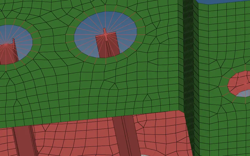
Fig: Bar element
d & e: Concentrated mass
At section d and e, a CONMASS property is applied to the master node (independent RBE2).
To create the conmass:
1D - masses - select node - mag = 10 - eletype = CMASS1 - create
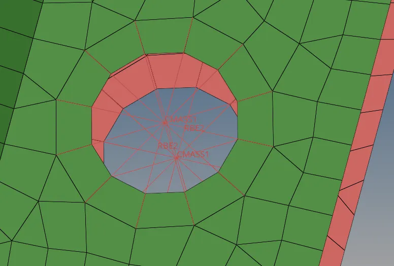
Fig: Concentrated mass
f: Spring element
A spring element ca be created as follows:
1D - spring - (select a node from both bracket components) - ele type - dof where the spring constraints - create
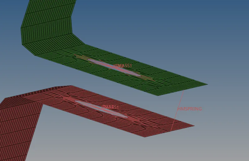
Fig: Spring element
CONCLUSION
Hence the entire solid component was extracted for mid surface and meshed using mixed shell elements either quads or trias and finally all 1D elements created were assigned individual cross-section and individual properties.
The thickness of the mid-surface and the 3D representation of the 1D elements are visualized from the bottom toolbar.
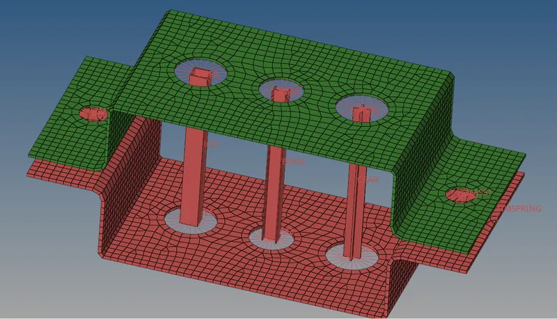
Fig: Pre-processed model