Week 4- Challenge
OBJECTIVE :
Meshing a given component and creating 1D elements on the same with a particular cross-section and DOF.
PROCEDURE:
A] Importing the given component :
- Go to File > Import > Geometry > Select the required IGS file > Import
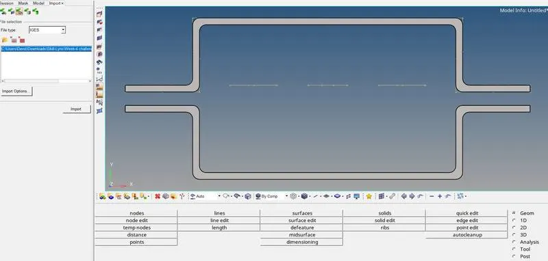
For 2D meshing, its essential to create/extract the mid-surface first, and then proceed with auto-cleanup and meshing.
B] Extracting the mid-surface of the component:
- Go to delete > solids > All > delete entity
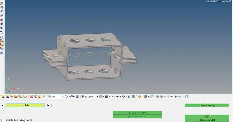
- Go to Geom > midsurface > extraction options > select offset+planes > go to auto extraction > select surfs > select the surfaces in the model space individually > click extract .
Mid surface created are mentioned in the model tab which can be renamed , by right clicking on the component name > Rename
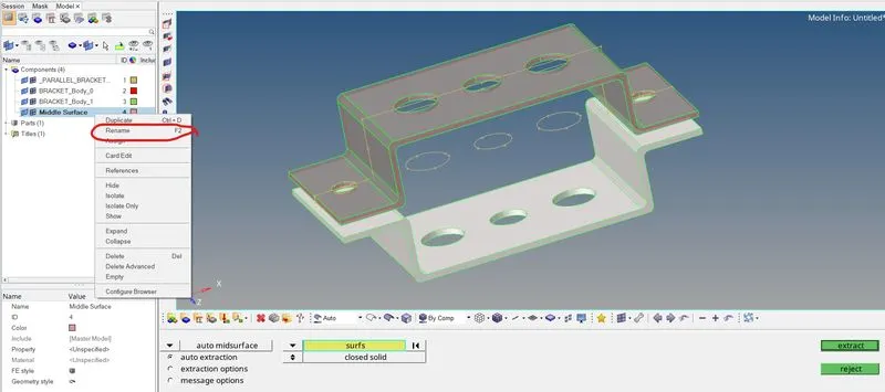
To avoid the mid-surfaces being created in a single component ,
- Right click on Components in Model tab > create > enter component name
- Go to Tool > organize > surfs > select the surface to be moved in model space > set the dest component (newly created component) > move
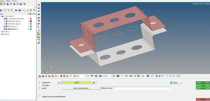
C] Meshing the given component :
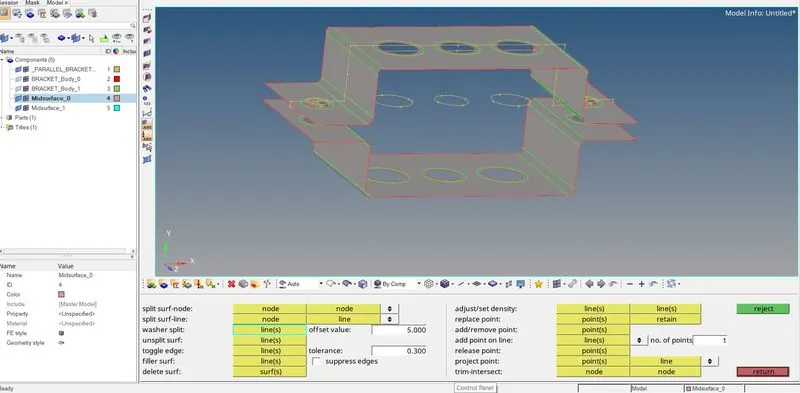
Before meshing , its always best to create washer splits around holes if any
- Go to Geom > quick edit > In washer split, set the offset value to 5 > select the lines/geometry in model space
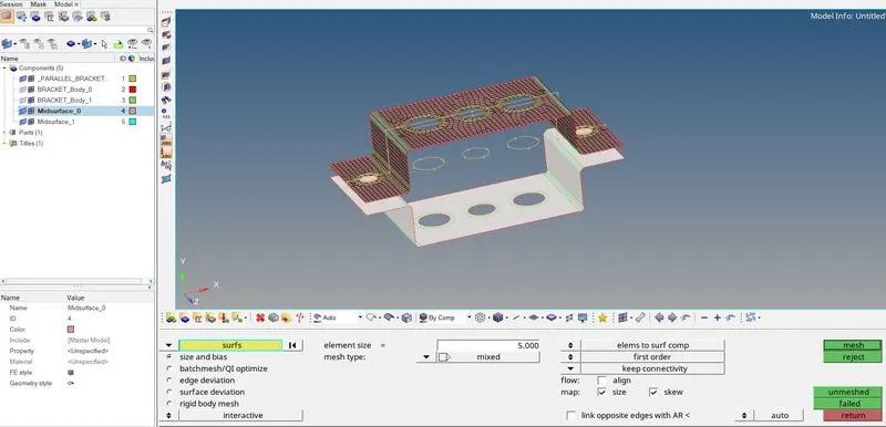
- 2D > automesh > surfs > select the surfaces individually > set element size 5 mm > mesh
D] Creating elements with particular cross section and DOF:
1) Creating Material -
- Right click on empty space in model tree > Create > Material
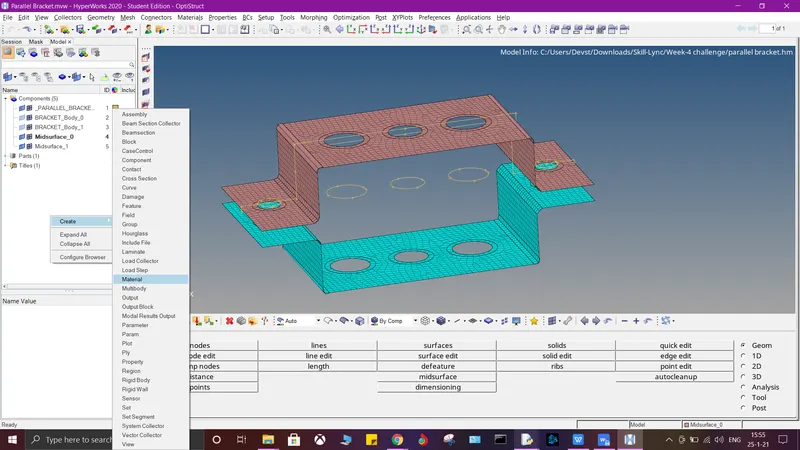
- Enter element name as "Steel" , enter E = 210000 in the parameter tab also Nu = 0.3 (these parametric values are default values)
2) Creating Properties:
- right click on model tree > Create > Property
We need to create properties for both midsurfaces , rod, beam, bar and spring and also set their card images respectively as given below-
| Sr No. | Property Name | Card Image |
| 1 | Bracket_1 | PSHELL |
| 2 | Bracket_2 | PSHELL |
| 3 | Bar | PBAR |
| 4 | Rod | PROD |
| 5 | Beam | PBEAM |
| 6 | Spring | PBUSH |
Before proceeding to create bar, rod, beam elements and masses , it is essential to create rbe2 and rbe3 links first as required.
3) Creating Bar element :
- 1D > rbe3 > select the nodes > uncheck dof1 , dof2, dof4, dof5 > create
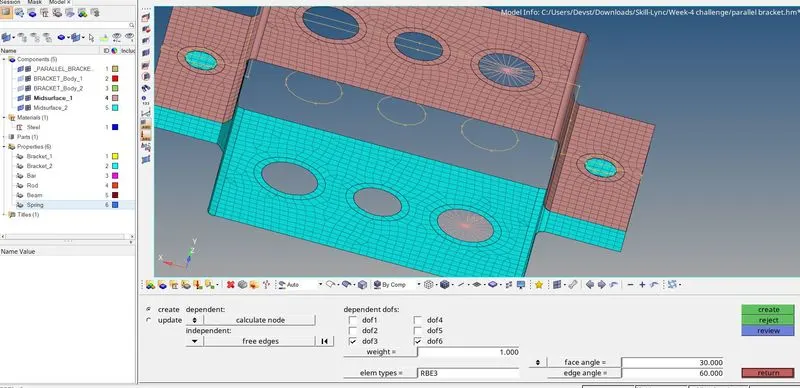
- 1D > bars > select the nodes > set property as "Bar" (previously created) > set elem type as CBAR > select the vector nodes for orientation.
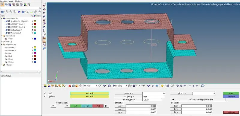
4) Creating Rod element :
- 1D > rigids> select the nodes > uncheck dof1 , dof2, dof3 > create
- 1D > rods > select property as "Rod"(previously created) > select elem type as CROD > create
5) Creating Beam element:
- 1D > rbe3 > select the nodes > uncheck all dof's > create
- 1D > bars > select the nodes > set property as "Beam" (previously created) > set elem type as CBEAM> select the vector nodes for orientation.
6) Creating Spring element:
- 1D > springs > set property as "Spring" and elem type as CELAS1 > select nodes
7) Creating masses :
- 1D > masses > enter mass magnitude 10 > set property as Bracket_1 or Bracket_2 and set elem type as CMASS1 > select nodes > create
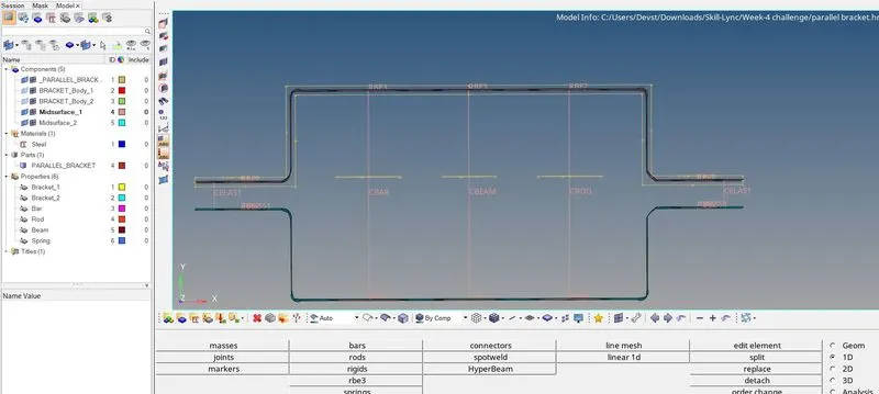
8) Creating Cross-sections :
1D > Hyperbeam > select 'Standard section' > set standard section library as HYPERBEAM > create
(i) For Box cross-section :
- set the values in the parametric definition table as follows-
Dimension a= 12 mm
Dimension b=10 mm
Thickness t= 0.75 mm
(ii) For I section :
- right click on Entities space on the left > create > Standard Section > HyperMesh > Standard I section
- set the values in the parametric definition table as follows-
Dimension a= 8 mm
Dimension b= 10 mm
Dimension c= 8.5 mm
Thickness t1= 0.75 mm
Thickness t2= .6 mm
Thickness t3= .6 mm
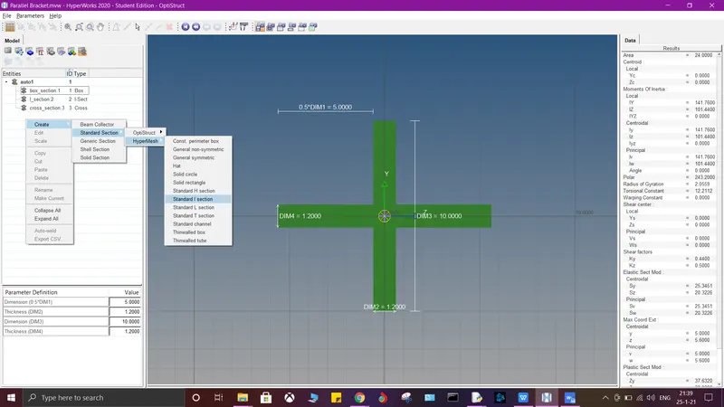
Similarly,
(iii) For X section:
- set the values in the parametric definition table as follows-
Dimension DIM1= 5 mm
Thickness DIM2= 1.2 mm
Dimension DIM3= 10 mm
Thickness DIM4= 1.2mm
9) Assigning Cross-sections to the respective Components:
Go back to the model view > select each element from the created properties > set the Beam Section in the parameters below as the respective section mentioned.
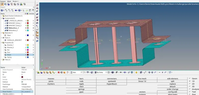
RESULT :
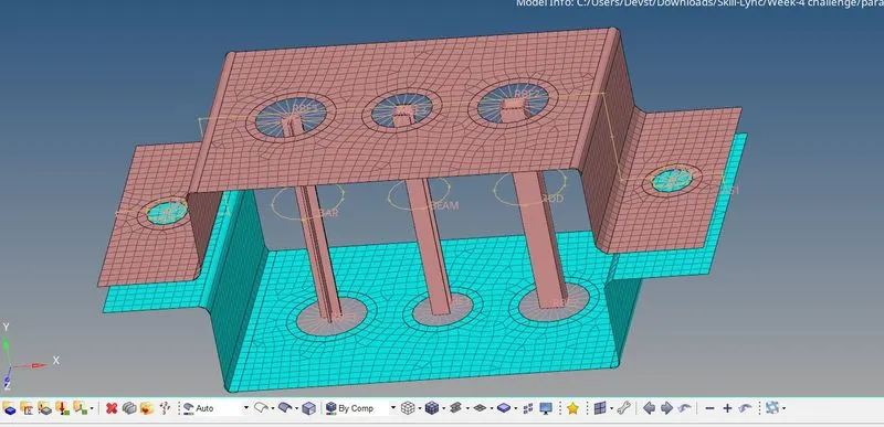
- The Geometry was imported and meshed accordingly.
- Given 1D elements were created on the components with respective cross-sections and DOF's as mentioned.