Week 4- Challenge
Aim:
To mesh the given component.
To create a 1D element,cross section and dof.
Procedure:
The given model is made to import on the hyperworks. After importing thr model something looks like this.
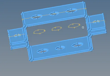
The wireframe which is not necessary for this process so it can be deleted.
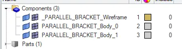
Now for deleting the solid surface in the given component go to delete-> solids-> delete entity.
Now the solids surface at the given component is deleted.

Now creating a midsurface for the component for that go to Geom-> midsurface-> select the surface and click extract.
Now after the midsurface the component looks like this. Midsurface is extracted for the features splits that extracted surface at the boundary of thickness transition so that the underlying elements are able to update the shell thickness property as the thickness changes on either side of the split.
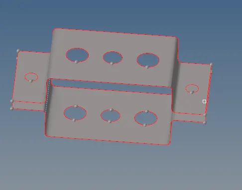
Now the given component is done with the deleting the solids and with taking the midsurface.
The process that is done is meshing the component with the given element size. For that go to 2D-> Automesh-> select the surface to mesh-> click mesh. That particular surface is meshed.
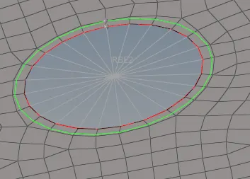
After meshing the surface 1D element is made to the respective areas that is creating a rigid body. For the go to 1D-> rigids-> multiple node and calculate node-> and create the rigid body.
Rod element:
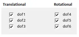
According to the given, each separate hole is made with the separate rigid body. For the first one it is made with the RBE 2 link. For that the dof is separated with translational and rotational. In case one it is said translational dof shold be constrained, so off rotational.
A rigid body with made to connect with the upper bracket and the lower bracket by going to 1D-> Rods-> selecting the node 1 and 2-> there creates a rod with change in element type as CROD.

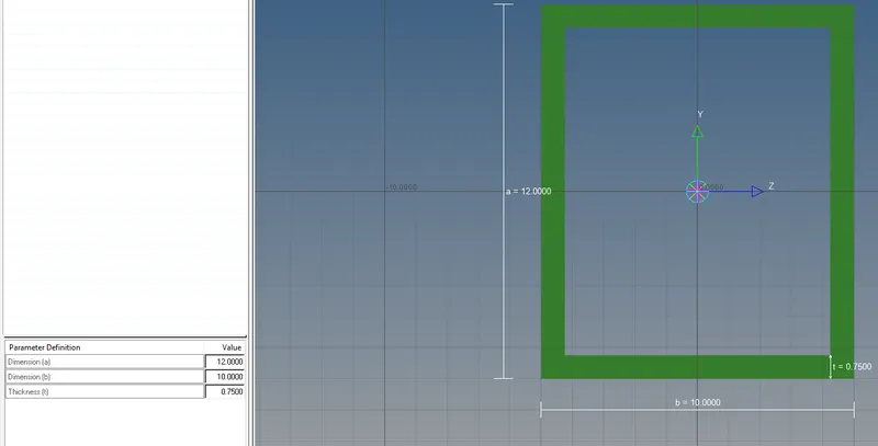
With the cross sectional box for that 1D-> hyperbeam-> Standard Section-> standard section library(HYPER BEAM)->standard section type(thinwalled box). Enter the given value, the values is assumpted automatically and a box section is created.

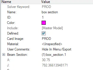
Now creating the property for the cross sectiona box and filling the card image as PROD and beam section as cross section box.
Now updating the rod element go to rod-> update -> elem type(PROD)-> Property(select the file which is created in hyperbeam)-> now click update. After update click 1D detailed translational element shows the rod in 2D.
Beam element:
At the second place RBE 3 link is made to connect as rigid. For that go to REB 3 create a rigid body with all DOF as constrained. The rigid body is made on the both the upper and lower bracket.
Now after creating the rigid body go to 1D-> bars-> elem type(CBEAM)-> and oritentation-> and a rod is created.
Now go to hyperbeam-> Standard Section-> standard section library(HYPER BEAM)->standard section type( standard I section).
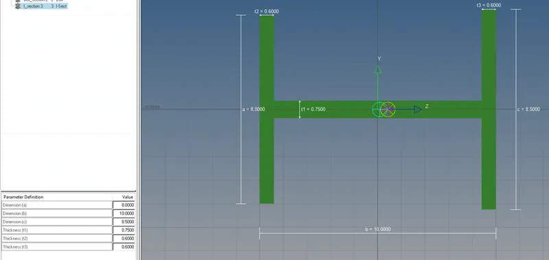

After entering the given values at the respectives places at the hyperbeam,there creates a I section rod. Now creating the property changing the card image as PBEAM and Beam section is called fromt the hyperbeam.
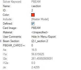
Now the beam is updated with 1D-> bar-> update -> elem type(CBEAM) and Property(i section)which is created at the time of hyperbeam-> click update.
Bar Element:
With the given requirement it is made that the DOF X and Y is made to constrained. With the X and Y axis constrained the RBE 3 link is made at the third hole.
Now the cross section is made with 1D-> Bars-> changing the elem type as CBAR -> and keeping the oritention along the RBE3 link then creates a rod along the link.
Now go to hyperbeam-> Standard Section-> standard section library(OPTISTRUCT)->standard section type( CROSS).
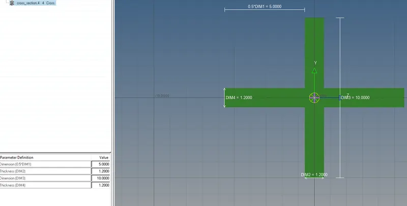


Now creating the property, changing the property name as PBAR and assigning the Beam section with the cross section made in hyperbeam.
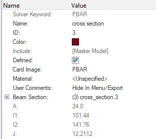
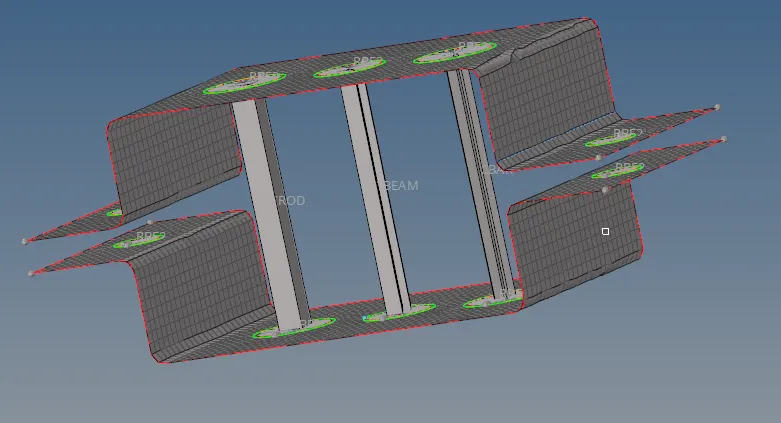
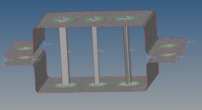
After all the process is done there creates a cross section at the third hole. After working with the Bar,Beam and Rod element the final piece looks likes this.
Mass at d & e
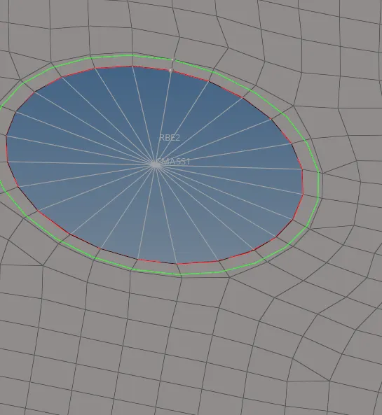
With the RBE 2 link d & e is made a rigid body. Go to 1D-> Rigid-> select the node-> create-> there creates a rigid body. Now giving the mass at RBE2 link for that go to 1D-> Masses-> select the link and mass(10)-> elem types(CMASS1)-> click create. There creates a mass on the RBE2 link.

Spring Element:
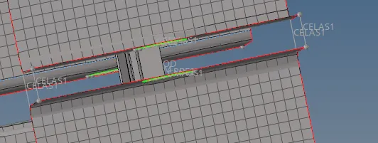
Connecting the free parts with the spring element i.e., go to 1D-> Spring-> select the two point, automatically creates a spring.

Result:
The complete piece
Conclusion:
After working with the mesh creatind a 1D element such as Rod,Beam and Bar element and giving the mass and spring between the bracket the required output is obtained.