Week 4- Challenge
AIM:
To mesh the given component with the size of 5mm and to create a 1D element on the element with the given cross section and DOF.
Solution:
-Initilaly we import the model form the files which is of .IGES format.The imported model is as below:
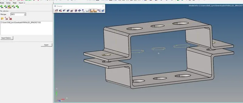
-Here now we delete the solid surfaces by selecting the delete icon>select the solids and then press delete entity.
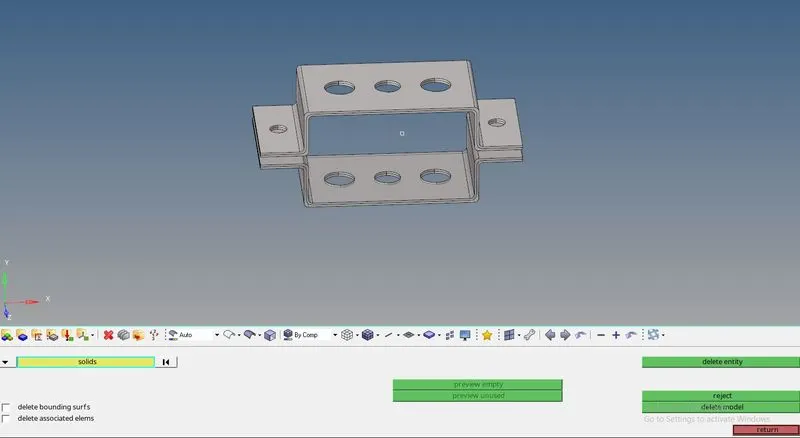
-Now we need to define a mid surface to the model by uisng the geometry>midsurface>select one component and click on create midsurface.For getting better mid-surface click on offset+planes.

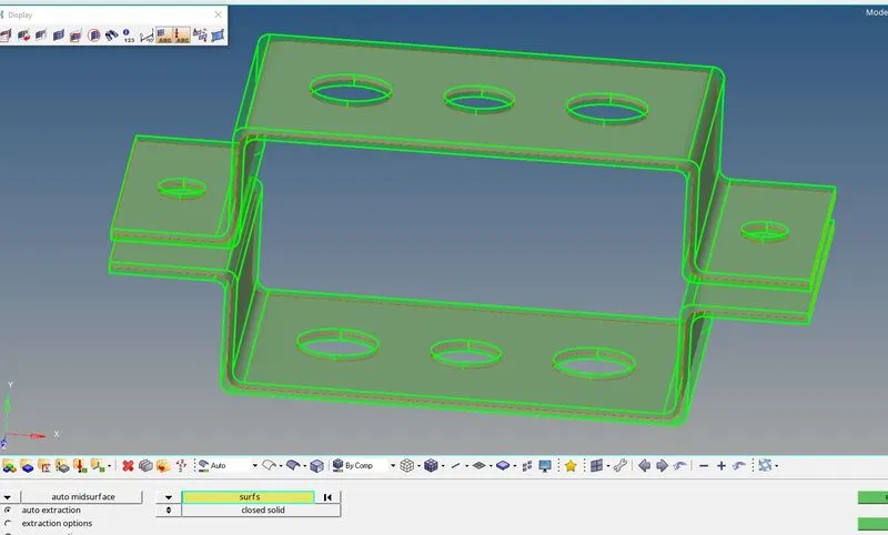
-Now we delete the parallel_bracket_body_0 for which mid-surface was created and we rename it as Bracket_1.Similarly we delete the parallel_bracket_body_1 for which we again create a mid-surface and finally rename it as Bracket_2.
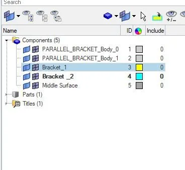
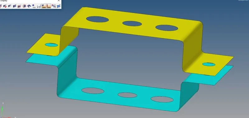
-Now the model with new name will be as follows:
-Now we need to assign materail and property to it by using the option right click on browser>create >material.similarly for property also right click on browser>create>property and enter the value dailoug box parameters.
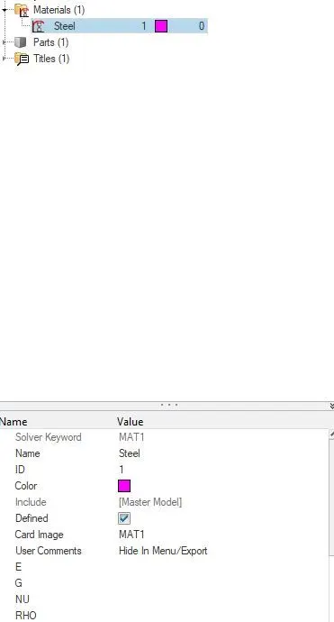
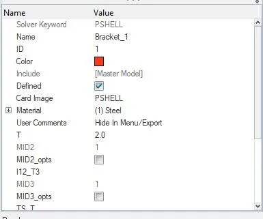
parameters for Bracket_1 is as follows:
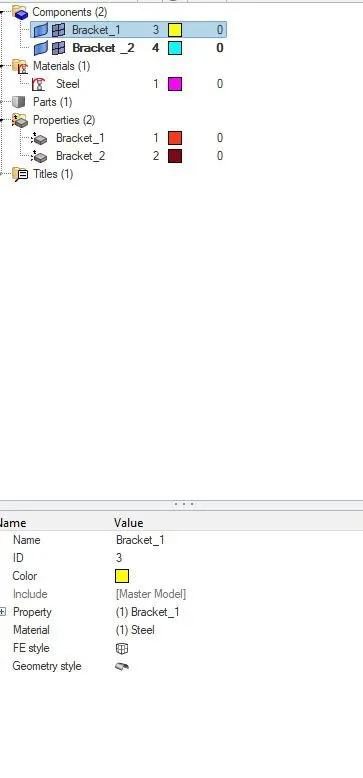
-Similarly for bracket_2 is as follows:
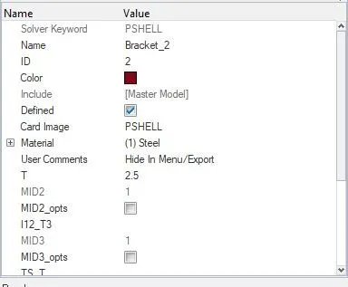
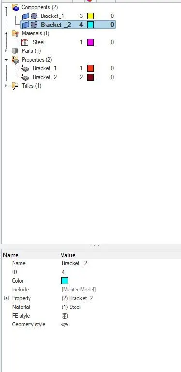
-In the above image we can see that the for Bracket_1 we have given a thickness of 2.0mm where as Bracket_2 we have given a thickness of 2.5mm.we have card image as MAT 1 in material where as in properthy we have given P SHELL.
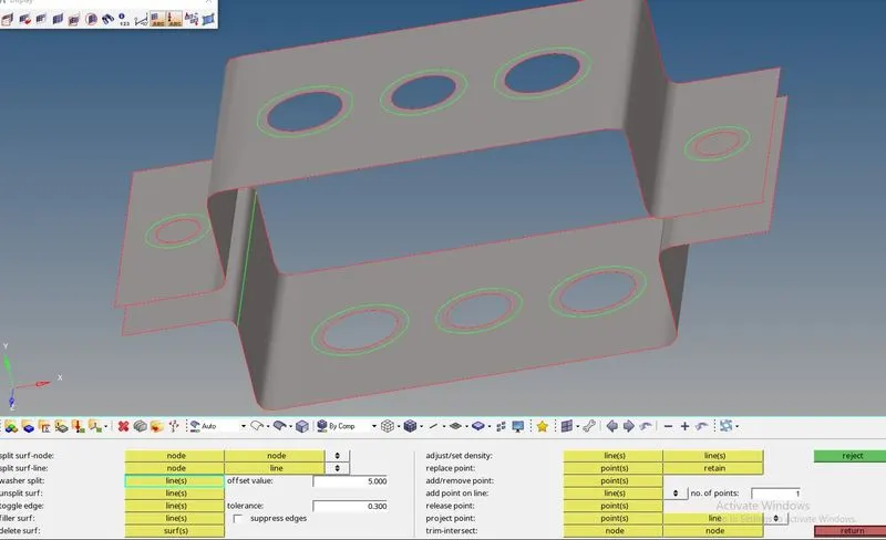
-Now we need to hole the component in the component by using the command mainmenu>geometry >quck edit>washer split>line>give offset values as 5>select the hole,now we can see a washer split being created.
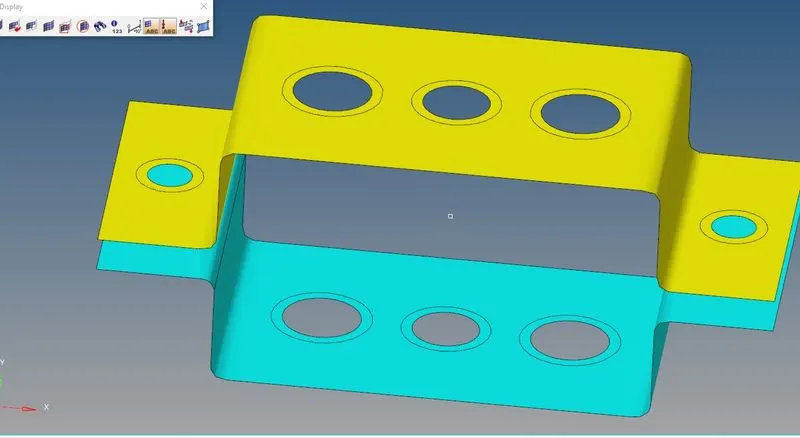
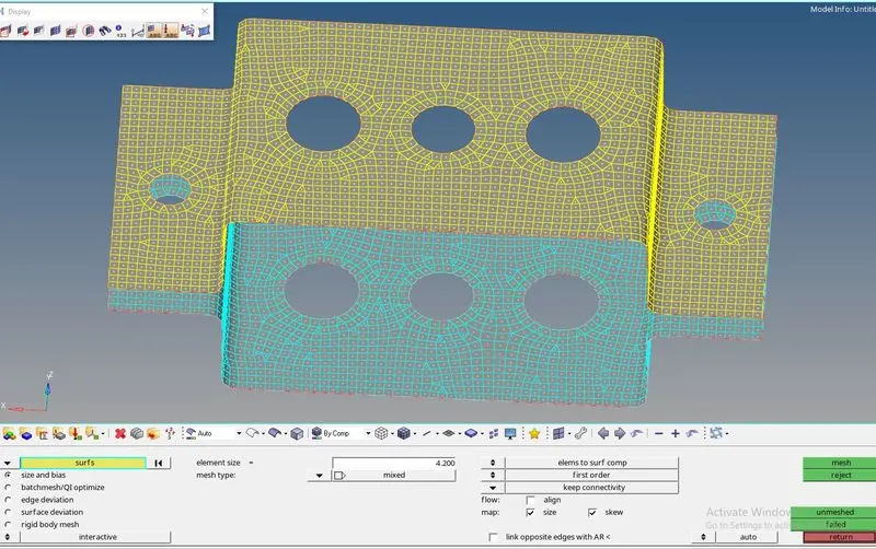
-Now to perform 2D meshing with an element size of 5mm in our case it is around 4.2 mm by using the command option menu page >2D>automesh>select type as mesh>select surface>all>mesh.
-Now to create a ROD element which is 1D in nature:
-Go to main menu>1D element>rigid(RBE2)element>create>independednt(calculate nodes)>dependent(nodes).select element types as RBE2.For translation type select only DOF1,2,3.Now select nodes by path.

Note:
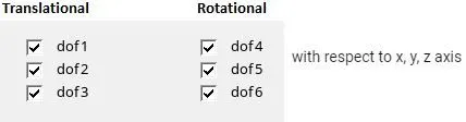
-But before clicking on create make sure that you select the model path where you want to add the 1D element by go to updatde >property >select the model.
The color difference in rigid body shows change in asigning RBE2.
Now to create ROD element:
-In main menu>1D>rod,In check element type give CROD and pick the center of two nodes of the plate and there by we can see that the ROD is created.

Now to give Dimension to the cross section box:
a=12mm,b=10mm,thickness(t)=0.75mm.
-Now got to hyper beam veiw>right click on browser>standard sectiin>hypermesh>Thin walled box.
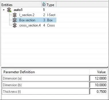
-Now thereby we will get the cross-section.
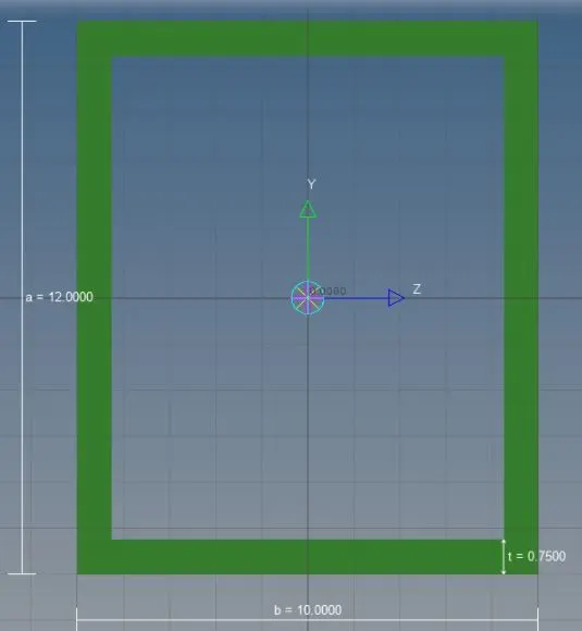
-Now we assign cross-section to rods:
-Right click on browser>create property>In card image selection>PROD,In beam selection>select the box saved in hyper beam.
-Now go to rods in 1D>select update>select rod element on screen>update.

-Beam element with all DOF and RBE3 link.
-To create RBE3 link go to 1D>RBE3 link>select all DOF,In dependent>calculate node,where as in place of independent>select Nodes by path.
-Give element type as RBE3.

-Now we need to assign beam element by using the command main menu page>1D>bars.

-Now in element type ,select CBEAM then pick the center nodes and give orientation then click TAB on keyboard and there by beam will be created.
-After that we need to create I cross-section for that go to Hyperbeam veiw>right click on browser>create>standard section>hypermesh>select standard I section and then we can assign the required values as below:
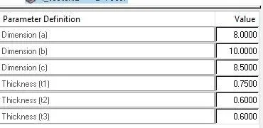
-Now we need to assign cross-section to the beam by right click on browser>property>assign card image as PBEAM in beam section and there by I section is created.
-Now go 1D>bars>select update.
-In property select I-cross section to beam property and then click on update.
-Now to create a bar element with x and y DOF with RBE3 link
-Go to main menu page>1D>select RBE3 link>selct x and y translation and deselect other dof's based on the given conditions.

-Similarly assign RBE3 element for Bracket_2.
-For creating the bar element,Go to 1D element>bar>select element types as CBAR.

-Now pick the nodes and also pick the orientation and then finally click on TAB.
-Now to define the inputs to the cross-section ,go to hyperveiw>create>standard sections>optistruct>cross.
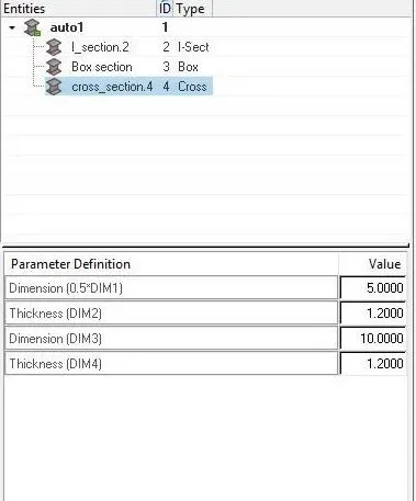
-Now to assign cross property to the bar for that we need to define a property by using the command right click on browser>create>property,a small dailog parameter box appears where we need to define the card image as PBAR.also in beam section assign to cross section which was created in hyperveiw.
Diag.
-Go to bars in 1D element>select update>select element>bar element.select property to cross-section.

-To apply mass of magnitude 10 with RBE2 link,for that we have to intially create node on d&e holes and then create a rbe2 link over it.

-Now pick up the nodes by going to mass in 1D element>and select the element type as CMASS-1.

-To join the two components by using the spring element,for that go to 1D>spring element>select the element type as CELAS1.And then select the nodes of the two components where you want create a spring joint.

-Now join where ever required.
The final model will look like as below:
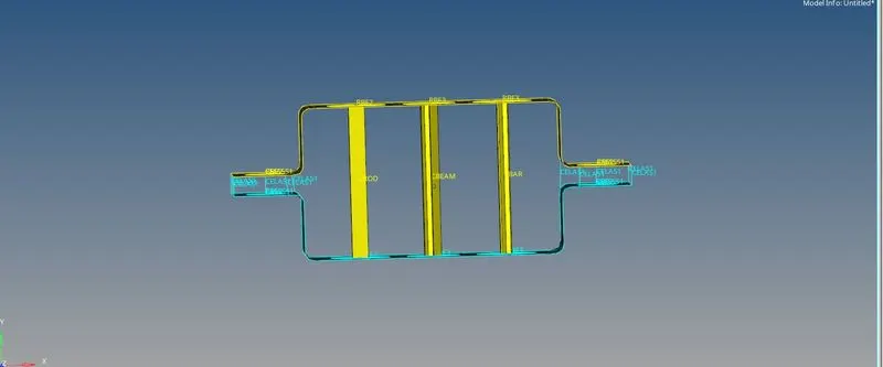
-Conclusion:
i)Created rigid links on the given component with varying DOF's.
II) understood how to create cross section using hyper beam veiw and also got an idea on how to assign rigid links and there by assign it to cross section