Week 4- Challenge
OBJECTIVE:-
Mesh the Given component with the Size of 5mm. Create 1D elements on the following component with given cross-section and DOF.
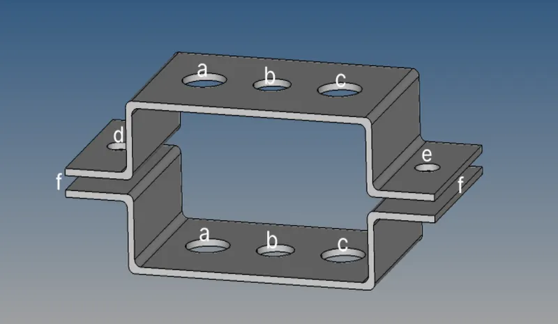
a. Rod element:- Translational DOF should be Constrained with RBE2 link
Cross-Section: BOX- Dimension a= 12 mm
dimension b=10 mm
Thickness t= 0.75 mm
b. Beam element:- All DOF should be constrained with RBE3 link
Cross-Section: I Section- Dimension a= 8 mm
Dimension b= 10 mm
Dimension c= 8.5 mm
Thickness t1= 0.75 mm
Thickness t2= .6 mm
Thickness t3= .6 mm
c. Bar element:- Constrain only x and y DOFs With RBE3 link
Cross-section: X section- Dimension DIM1= 5 mm
Thickness DIM2= 1.2 mm
Dimension DIM3= 10 mm
Thickness DIM4= 1.2mm
d. & e. Apply the mass of magnitude 10 with RBE2 link
f. Join the two components with Spring elements
PROCESS:-
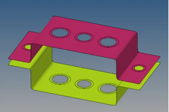
Figure 1 show the PID mode of the two bracket with all the geometry error eliminated and created washer.
- Clear all the topo error by auto-clear command or we can go by manual mode.
- It clears the geometry errors and creates the washer surface around the circle so that the mesh should be fine.
- Create a washer surface to the circles prsent on the mid surface to do meshing.
- We have to change the component colour for representation.
- Next step to do 2D shell meshing over the surface and eliminate the tria elements.
- With given target element size.
- Take care that there should not be any opposite trias, trias near-circular surface and trias on fillets.
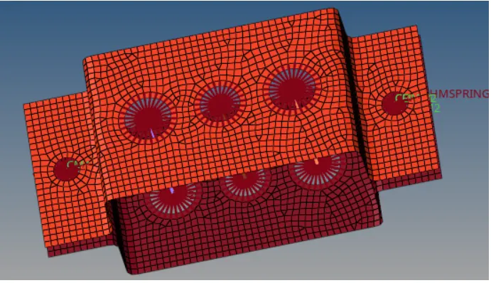
Figure 2 meshing done over the surface and RBE2 elements are created.
- As there 'a' point is mentioned we have to allot RBE2 elements with only a translation degree of freedom.
- And if their 'b' point is mentioned we have to provide RBE3 link with all degree of freedom.
- Therefore 'c' point is mentioned we have to provide RBE3 link with only x and y degree of freedom.
- We have done it by going to the 1D page and selecting the option of Rigid and RB3 respectively.
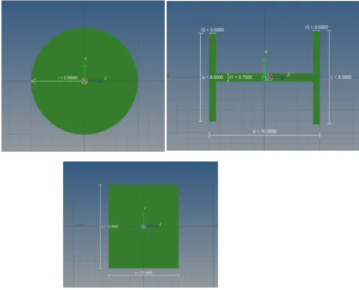
Figure 3 1D elements creation in hyper beam mode
- We have created a ROD,BAR and BEAM we have to go to the hyper-beam option directly.
- Inside the hyper-beam window, we select the cross-sectional area as given in the objective:
- Rod = Box Section
- Beam = I Section
- Bar = Cross Section
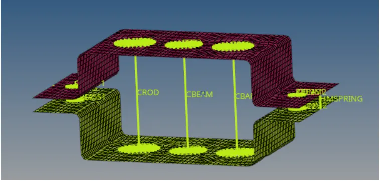
Figure 4 ROD, BAR & BEAM representation without thickness in comp mode.
- Connect both brackets with a rod, bar, beam and spring 1D elements.
- And this is not been seen as the rod bar beam we need to change the view to 1D details representation we can see the actual thickness given to the 1D elements for that we need to assign material like steel and properties to be updated and assign the properties to them.
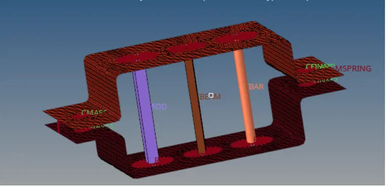
FIGURE 5 ROD, BAR and BEAM representation with thickness in property mode shwon.
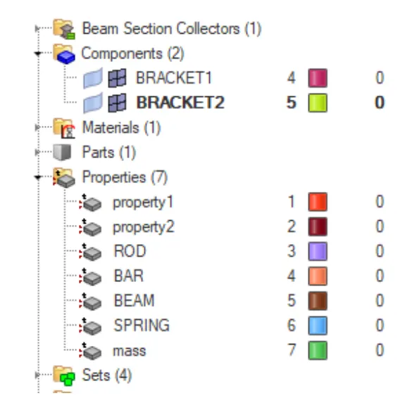
FIGURE 6 Components and property representation
CONCLUSION:-
- Created 1D elements over to join the surface
- Given thickness to them
- Created a property card and for representation given a different colour
- The function of the bar, beam and rod understood