Week 4- Challenge
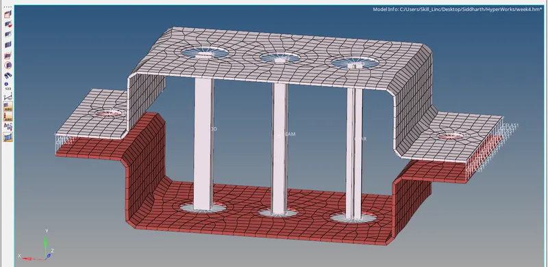
Objective: To deploy the mesh and create 1D elements on the following component with given cross-section and DOF
Procedure:
Import the given IGS file into Hypermesh from the model import option.
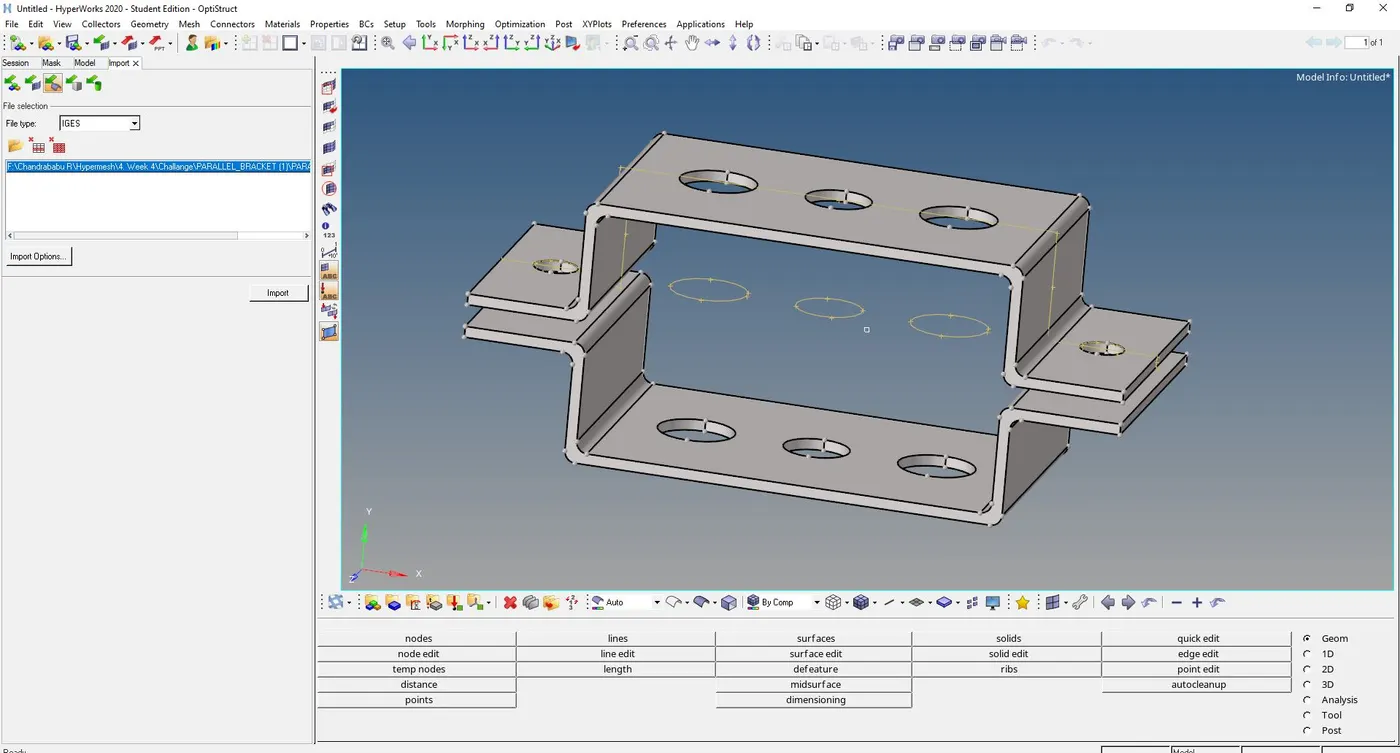 1. MidSurface Extraction: For the given component, extract the mid surface which is a sheet of 5mm thickness.
For extraction of mid surface, Auto mid surface (Geo>midsurface>Automidsurface) and select the surface.
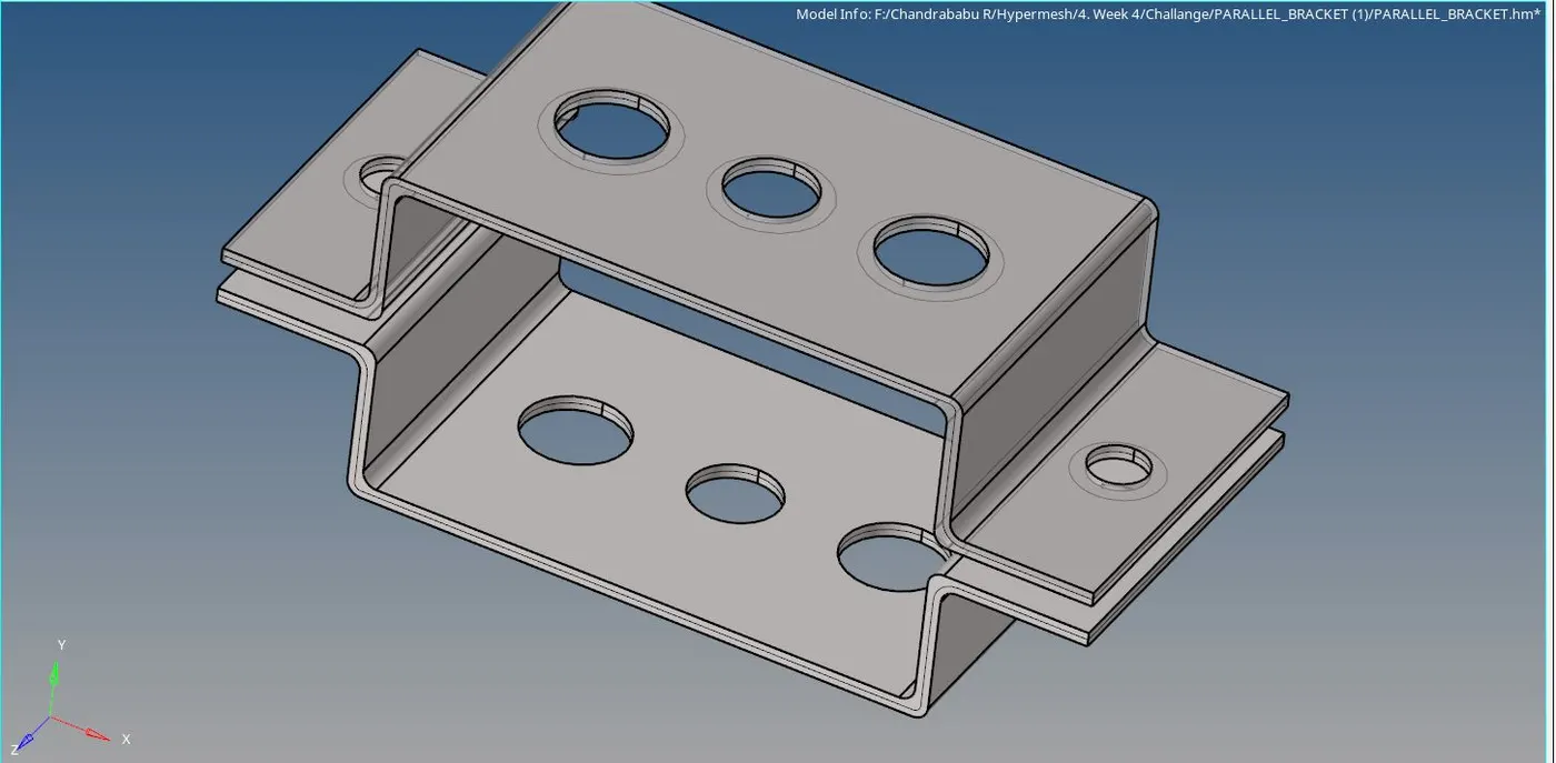
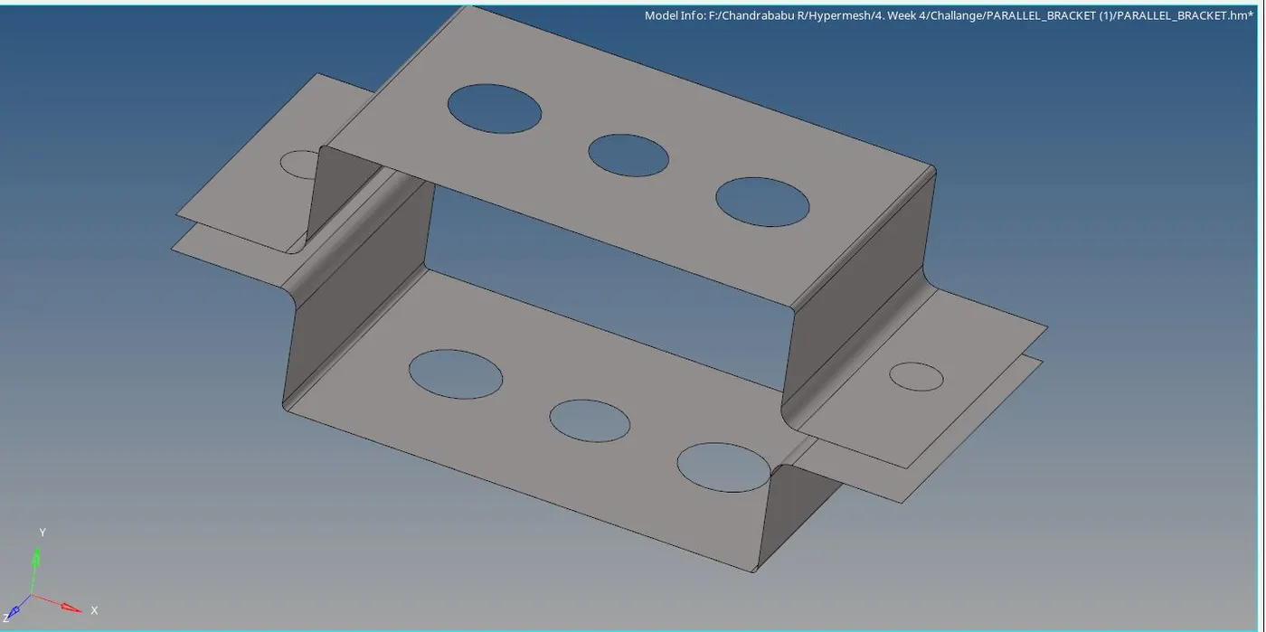
2. Washer splits created around holes and meshing
In the quick edit, the washer splits function is used with an offset value of 5mm.
Select the surface and give the default element size of 10 mm in the auto mesh.
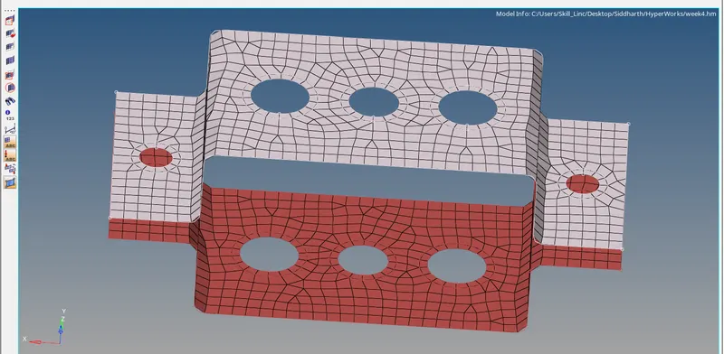
3. Creating RBE2 and RBE3:
RBE2: is the 1D element with infinite stiffness also called Rigid element
Create RBE2 by Rigids(1D>Rigids). For the location, we can select a single node or multiple nodes with a degree of freedom.

RBE3: RBE3's are interpolation constraint elements, where the motion of a dependent node is defined as the weighted average of the motions of a group of independent nodes. The dependent degrees of freedom and weighting factors can be specified or automatically calculated based on the geometry.
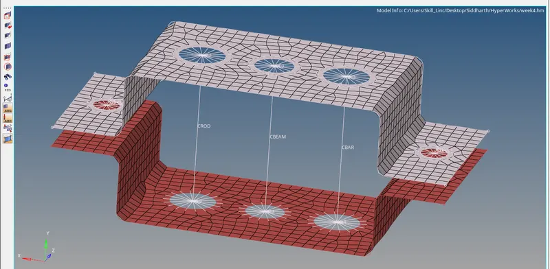
Cross-section and DOF:
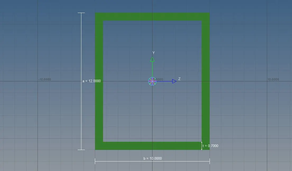
a. Rod element:- with only translational DOF and RBE2 link
Cross-Section: BOX- Dimension a= 12 mm
dimension b=10 mm
Thickness t= 0.75 mm
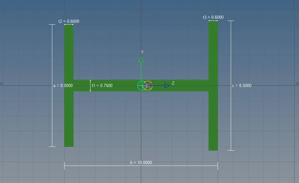
b. Beam element:- with all DOF and RBE3 link
Cross-Section: I Section- Dimension a= 8 mm
Dimension b= 10 mm
Dimension c= 8.5 mm
Thickness t1= 0.75 mm
Thickness t2= .6 mm
Thickness t3= .6 mm
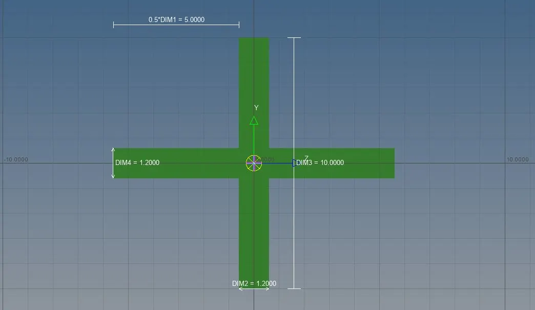
c. Bar element:- with only x and y DOFs With RBE3 link
Cross-section: CROSS section- Dimension DIM1= 5 mm
Thickness DIM2= 1.2 mm
Dimension DIM3= 10 mm
Thickness DIM4= 1.2mm
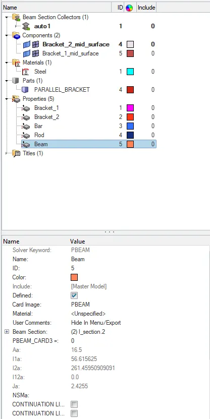
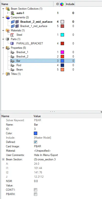
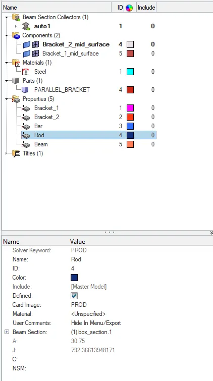
Create different properties for Beam, bar, and rod, and assign section respectively shown in the fig below.
Bar:
Rod:
Beam: