Creating Cross section and applying rigid links on Parallel Plate using Hyperworks Optistruct
Aim
- To understand 1D Elements, Links
- To understand how rigid links are given to a component
- To understand the role of Degrees of Freedom - Translational and Rotational
Objective
- To Create 1D elements on the given component with given cross-section and DOF
- Apply the rigid conditions on component
- Creating cross sections using Hyperbeam view
- Assigning cross section to rigid links
Given Model
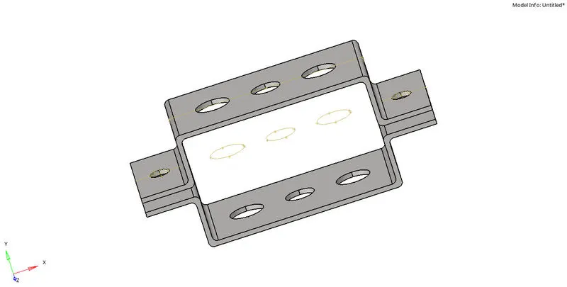
Wire frame was hidden
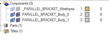
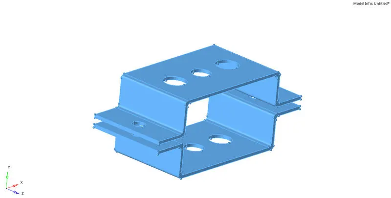
Solid surface was deleted

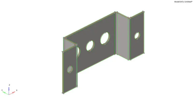
Midsurface creation

Select type - offset+planes for better mid surface

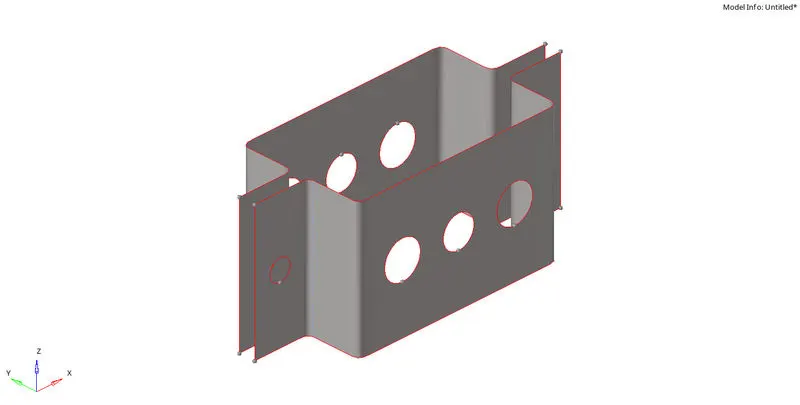
Mid Surface creation for Bracket
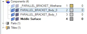
Delete the Parallel_Bracket_Body_0 for which mid surface was created and rename Upper_Bracket
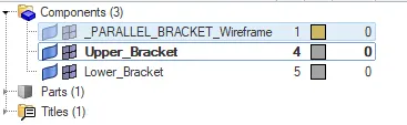
Similarly for delete Parallel_Bracket_Body_1 after5 creating midsurface and rename Lower_Bracket
Material and Properties were assigned
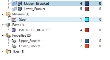
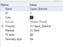
Thickness was assigned
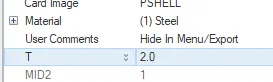
For Upper_Bracket = 2.0mm
For Lower_Bracket = 2.5 mm
Material Default values were assigned
Card image was given PSHELL in properties
Card image was given MAT1 in material
To the holes in component washer split of 5mm was given

2D Mesh of 5mm was done

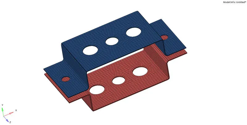
a. Rod element:- with only translational DOF and RBE2 link
Rigid is RBE2 Link in Hyperworks
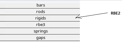

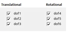 with respect to x, y, z axis
only translational DOF

Select caluclated nodes and nodes by path

Change the model when assigning rigid bodies respectively

The colour difference in rigid body shows change in asigning RBE2
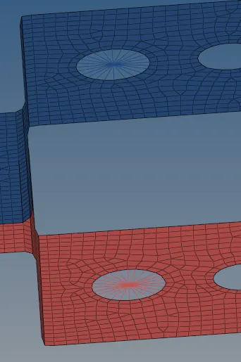
Creating Rod Element
In 1D go to rods

Check Element Type = CROD and pick the centre nodes of two plates; rod is created
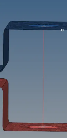
Cross-Section: BOX- Dimension a= 12 mm
dimension b=10 mm
Thickness t= 0.75 mm
Go to Hyperbeam View
Create-> standard section ->Hypermesh->Thinwalled box select it
Assign values in side window
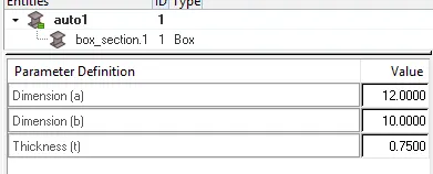
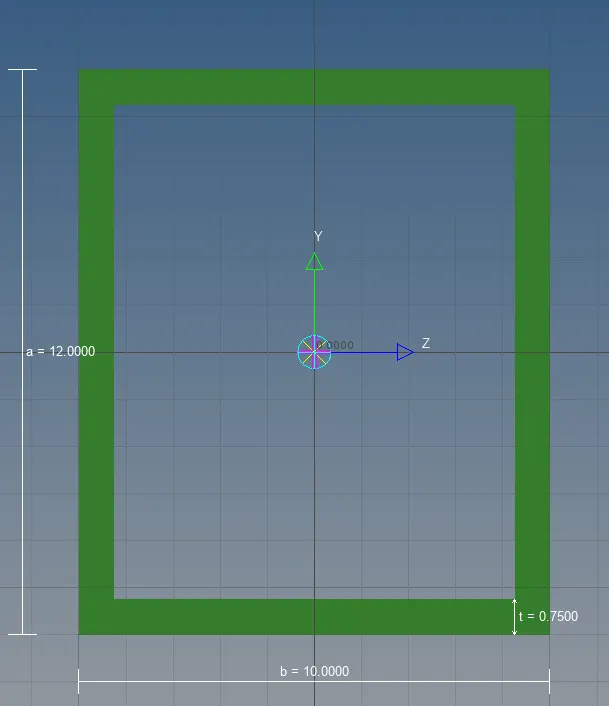
Cross section created
Assigning Cross section to Rod
Create a Property
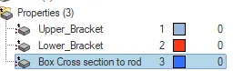
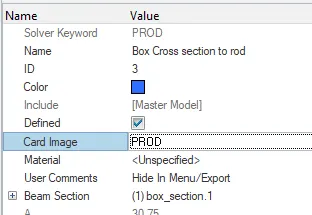
In Card Image select - PROD
->In Beam Selection - select box saved in hyperbeam
Go to rods in 1D
Select update -> Select rod element on screen and update

Cross section assigned to rod element
b. Beam element:- with all DOF and RBE3 link
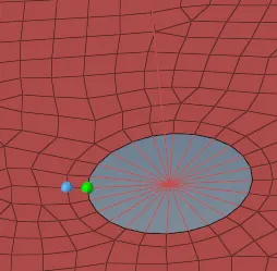
RBE3 link
->In 1D go to rbe3
with all DOF

by selecting node by path rbe3 link created
Assigning Beam element
To create beam element go to ->bars in 1D
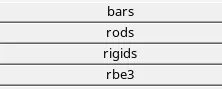
Select Element type - CBEAM

Pick center nodes and give orientation then click Tab on keyboard Beam will be created
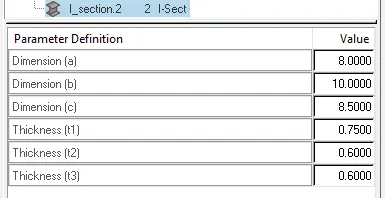
Cross-Section: I Section- Dimension a= 8 mm
Dimension b= 10 mm
Dimension c= 8.5 mm
Thickness t1= 0.75 mm
Thickness t2= .6 mm
Thickness t3= .6 mm
I Cross Section Creation
Go to Hyperbeam View window
-> Create ->Standard Section -> Hypermesh-> Select Standard I Section
Assign the required values
Assigning Cross section to Beam
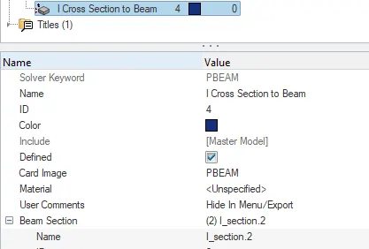
Create Property Assign card image -> PBEAM In Beam Section select I section created in Hyperview beam
Now go to bars in 1D
Select update

Select Beam Element
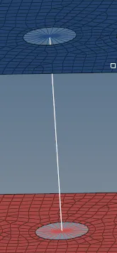
In Property select I Cross section to Beam Property

then click update
Cross section assigned to Beam Element
c. Bar element:- with only x and y DOFs With RBE3 link
Creating RBE3 Link with only x and y DOFs
Go to rbe3 in 1D select x, y translational and deselect other dof's based on given condition

Similarlly for Lower Plate assign rbe3 element
Creation of Bar Element
Go to bars in 1D
Select Element Type CBAR

Similarly as before pick nodes and pick orientation then click TAB
Cross-section: CROSS section- Dimension DIM1= 5 mm
Thickness DIM2= 1.2 mm
Dimension DIM3= 10 mm
Thickness DIM4= 1.2mm
In Hyperbeam View
-> Create -> Standard Section ->Optistruct -> Select CROSS
Assign required values
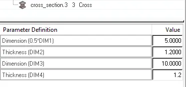
Assigning Cross to Bar
Create a Property In Card Image -> Select PBAR
In Beam Section assign to cross Cross section created in Hyperbeam view
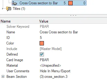
Go to bars -> select update -> Select elems -> bar element
Select Property to Cross Crossection

Cross section assigned to Bar Element
d. & e. apply the mass of magnitude 10 with RBE2 link
Create nodes on d and e holes and create rigid link /rbe2 link

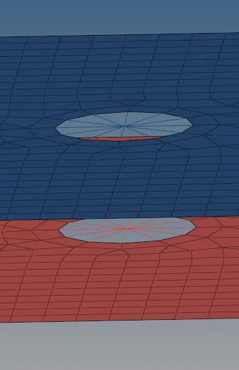
Mass of magnitude 10
Pick nodes
Go to masses in 1D -> Select Elem Type - CMASS1
Mass magnitude = 10
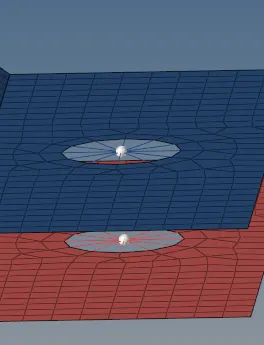

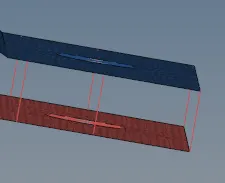
f. Join the two components with Spring elements
Go to springs in 1D
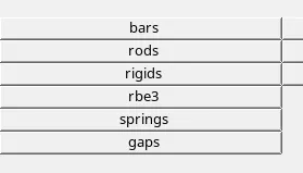
Select -> Elem Types CELAS1
Pick nodes

Join wherever required
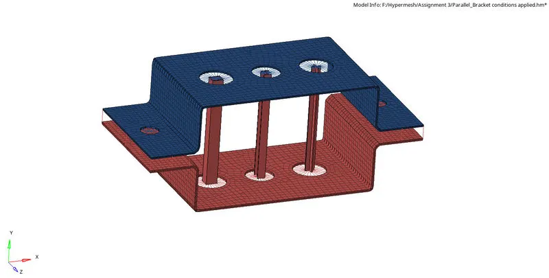
Creation of 1D elements of given component with given cross-section and DOF was done
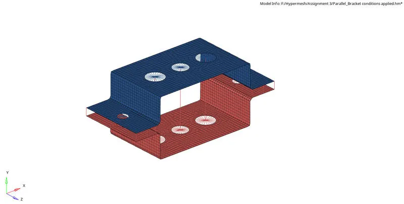
1D 2D Element Representation
Conclusion
- Created rigid links on given component with varying dof's
- Understood how to create cross section using Hyperbeam view
- Understood conditions on how to assign rigid link and assign it to cross section
References