Week 4- Challenge
AIM: To create the 1D element on the given component with the given cross-section and DOF.
KEYWORDS: Bar, Beam, Rod, Spring, Rigids (RBE2), RBE3, etc.,
SOFTWARE: Hypermesh
OBJECTIVE:
Initially, the given component is checked for geometry errors and do an auto cleanup tool.
After the geometry cleanup, Midsurface is created and meshed the model to create the 1D element.
The Material (Steel) and Properties are created for each part and 1D elements (Bar, Rod & Beam).
The 1D element is created by the Hyperbeam tool which is positioned in RBE & RBE3.
Assign the thickness for the shell element and 1D element.
INTRODUCTION:
The given component is checked for geometry errors and used an auto cleanup tool. After the cleanup, Midsurface is created and meshed the model with certain quality criteria in order to create the 1D element. Steel material is assigned for the component and properties are created for shell element and 1D element and assigned the thickness. The holes are connected with RBE2 & RBE3. 1D element is created in the rigid like a bar, rod, and beam. The mass is added with a magnitude of 10 and spring is connected between the two parts.
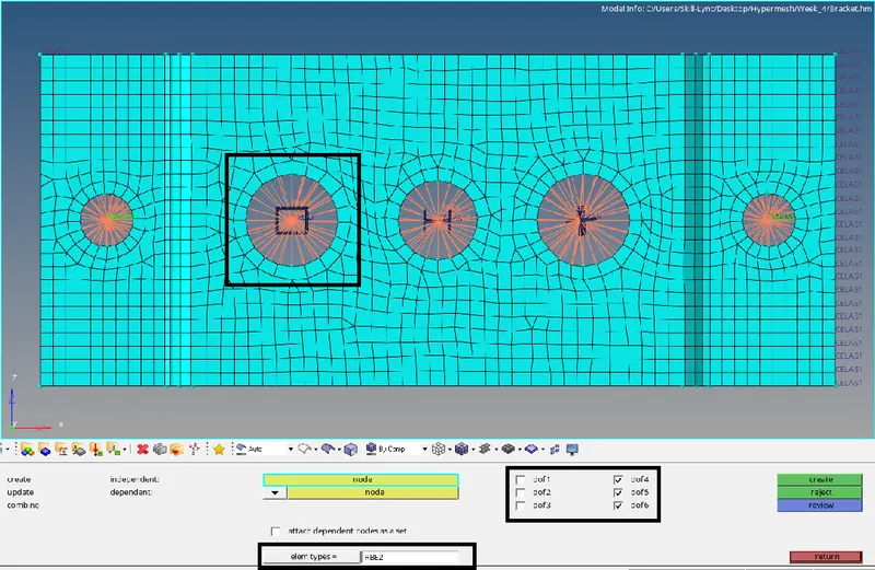
Figure 1: RBE2 with translational DOF
The above connections defines the RBE2 with only translational DOF which is connected to hole of each parts. The tool used is Rigid and selected the nodes related to the hole and connected.
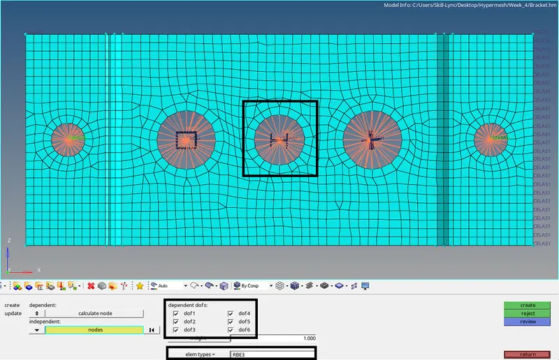
Figure 2: RBE3 with all DOF
The above connections defines the RBE3 with locked DOF which is connected to hole of each parts. The tool used is RBE3 from 1D element and selected the nodes related to the hole and connected.
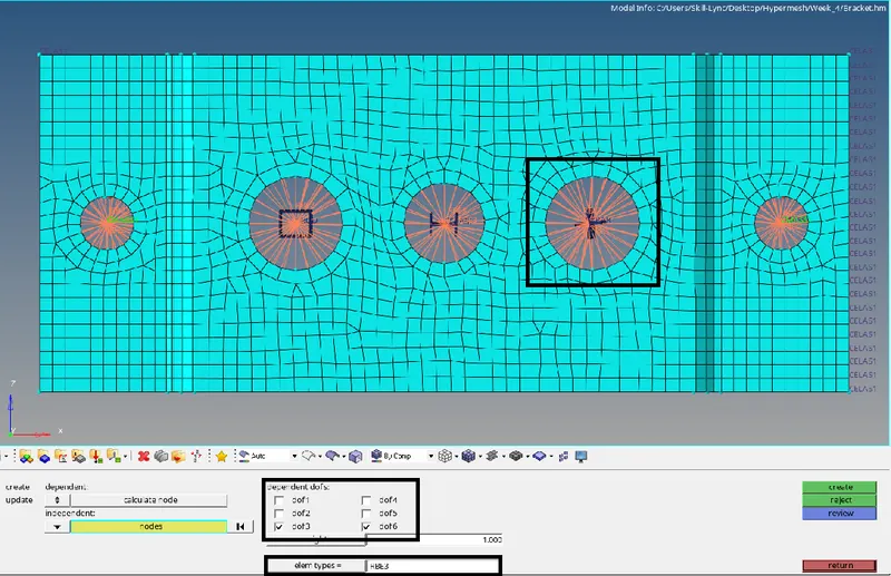
Figure 3: RBE3 with X & Y DOF
The above connections defines the RBE3 with locked Z DOF which is connected to hole of each parts. The tool used is RBE3 from 1D element and selected the nodes related to the hole and connected.
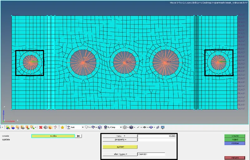
Figure 4: Mass added for RBE2 link
The Mass is added to the node which is conncted with the RBE2 link with a magnitude of 10 and element type used is CMASS.
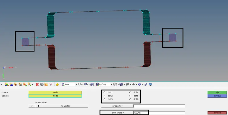
Figure 5: Springs are connected between the parts
The Springs are connected with equal number of nodes of each parts, which as some stiffness in Y-direction. The element type used is CELAS1.
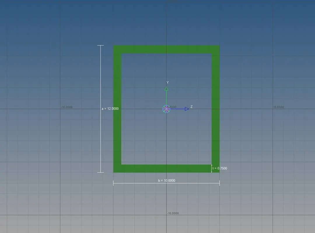
Figure 6: Rod element Cross-section
The above box cross-section defines the Rod element which is connected to the RBE2 link. The tools used is Hyperbeam by using thinwalled box standard section type.
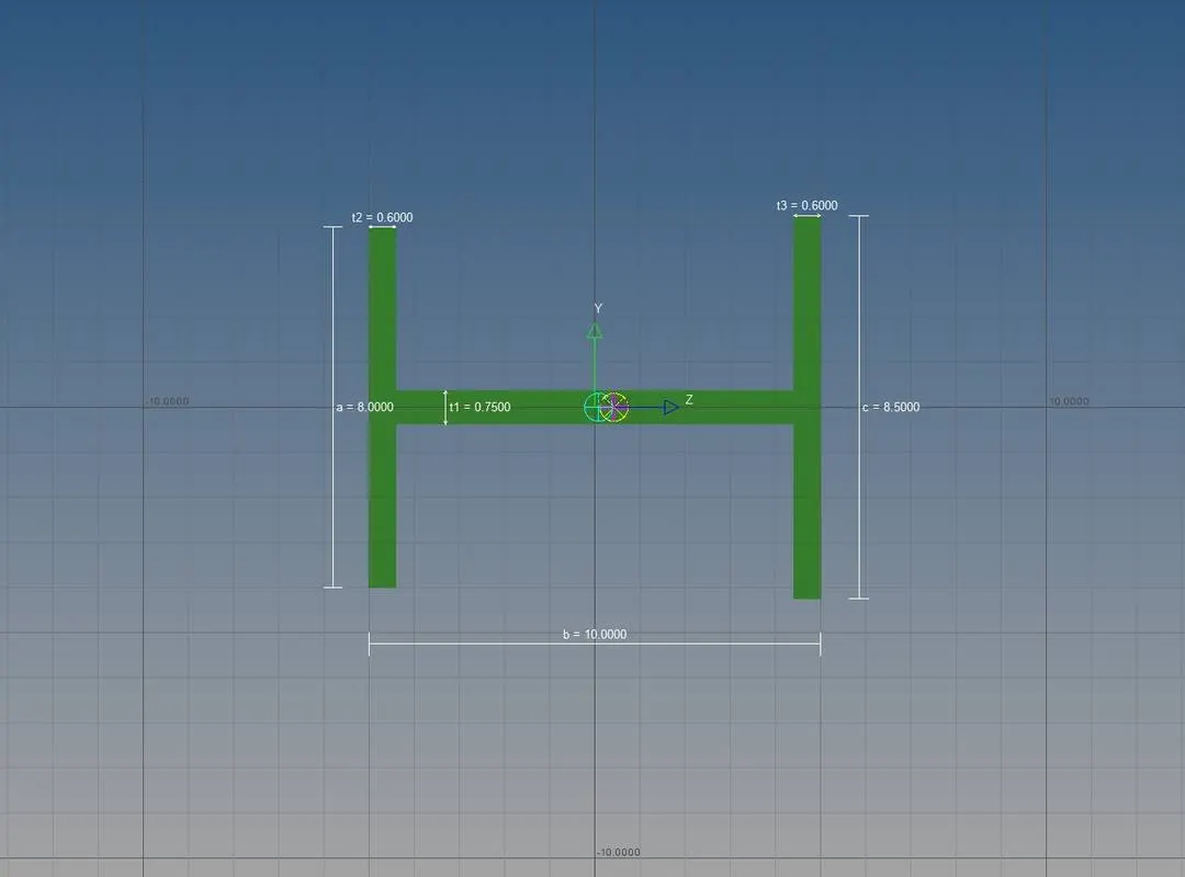
Figure 7: Beam element Cross-section
The above I cross-section defines the Beam element which is connected to the RBE3 link. The tools used is Hyperbeam by using standard I section type.
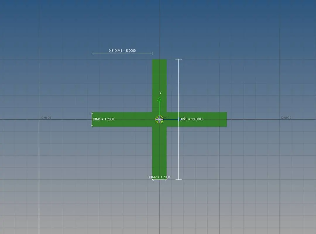
Figure 8: Bar element Cross-section
The above cross-section defines the Bar element which is connected to the RBE3 link. The tools used is Optistrut by using Cross standard section type.
RESULT:
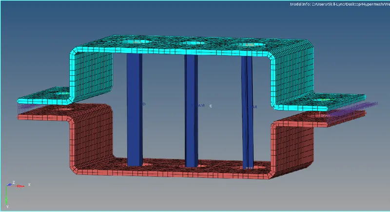
Figure 9: Model with assigned thickness
The above model shows the thickness assigned parallel brackets with connected 1D element (Bar, Rod & Beam), Springs, Rigids & RBE3 links. Initially, the Material (Steel) and Properties are created for the brackets and 1D elements. The 1D elements are created based on the cross-section.