BEAM , ROD and BAR Creation in Hypermesh
AIM
Create 1D elements on the following component with given cross-section and DOF.
- Firstly we need to import the geometry in Hypermesh and check for any geometrical error present in the CAD model and use Autoclean to repair the model.
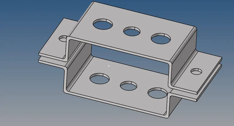
- Geometry imported is shown below:
Part -1: Midsurface Creation and Meshing
Midsurface tool that allows to find and extract surfaces from single thickness thin solid geometry.
We can use the Midsurface tool from the Geometry menu to create it with the default setting provide in it.

- It will extract the mid surface from the system and create a single component.
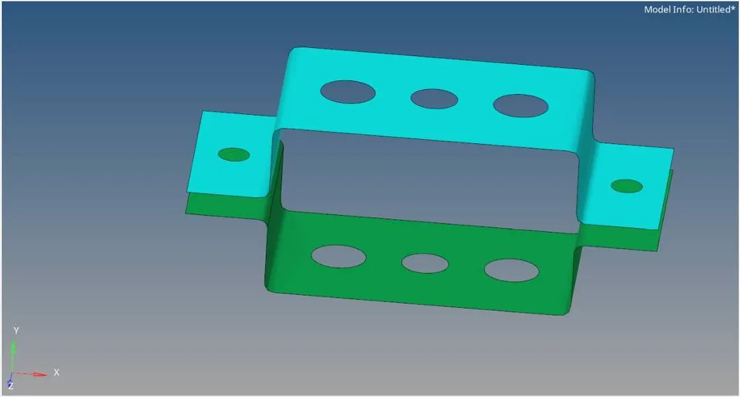
- It will create a single part, to create two parts, we will create two-component, in the window, and use the component option to move surface two different components as Part_1 and Part_2.
- After that, we will create the washer split around the hole to capture geometry properly.
Part -2: 2D Automesh
Mesh is used to discretizing the model on which equations are solved. 2D Mesh is created which is present in the Mesh Panel of Hypermesh.

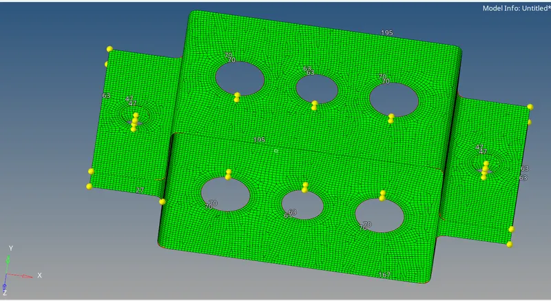
Element size is selected to be 2 mm, with mixed mesh to capture sharp corners if present.
After creating the mesh, element density around the hole is adjusted to capture the hole accurately.
Mesh created is shown below:
Beam, rod, and Bar Element Creation
Firstly we need to create the RBE2 and RBE3 elements in the given places as described in the question problem for load distribution.
RBE2 and RBE3 are rigid links in FEM used for load transfer. These elements, in fact, will not deform as they are considered to be infinitely rigid (diamond under atmospheric pressure for example even though it's not infinitely rigid) and the sole purpose of these elements is to transfer the loads between the grid points or nodes. RBE2 transfers the loads in such a way that all the slave (dependent) nodes have zero relative deformation after the loan application. Whereas RBE3 transfers the load using a weighted average of slave nodes(independent nodes) position.
RBE3 and RBE2 can be created from the 1D submenu present in the Mesh panel.
RBE3 creation panel is shown below:

Nodes are selected around the hole with the path selection option of nodes in the selection and select the degree of freedom as described in the problem.
For ROD
only translational DOF is selected for ROD.
For BEAM
All degree of freedom is selected for this with translational and rotational.
For BAR
Only X- and Y- degree of freedom is selected.
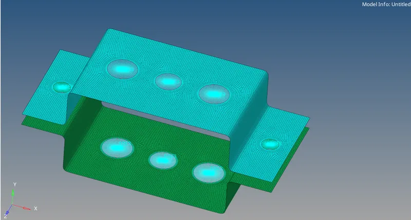
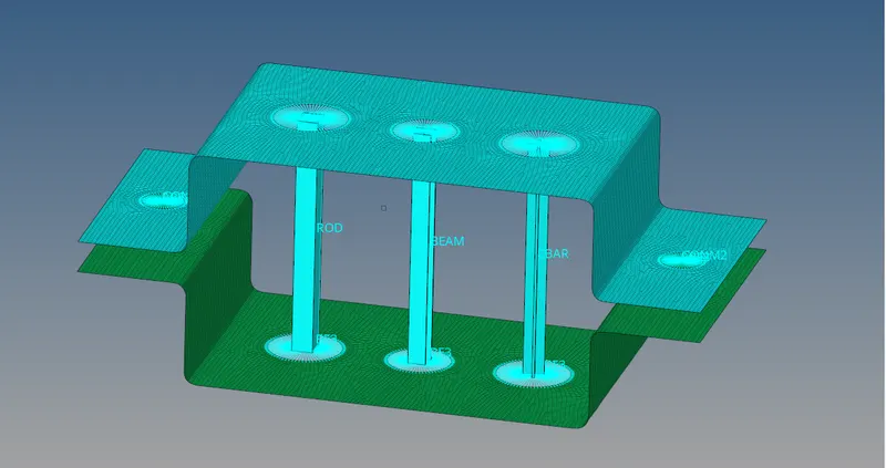
- After creating RBE3 and RBE2 elements it is shown below:
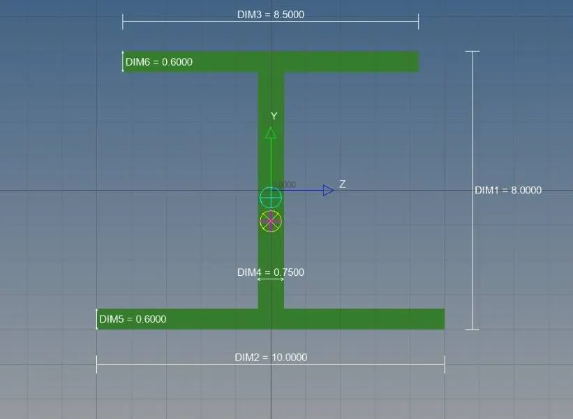
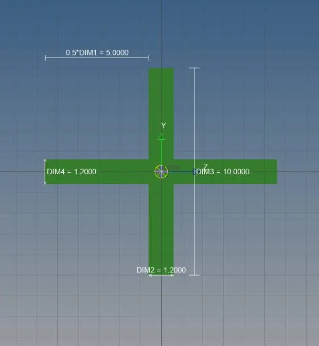
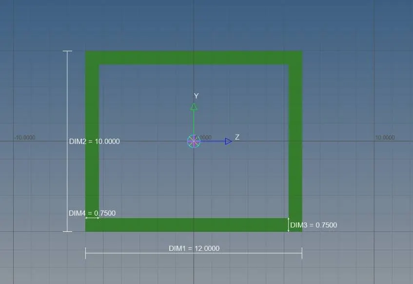
- Now we will create BEAM, ROD, and BAR with the given dimensions in the Hyperbeam window, which we can open from the Properties menu.
BEAM
Cross-Section: I Section
BAR
Cross-section: CROSS section
ROD
Cross-Section: BOX
- After creating these elements, we have created three different properties for Bar, Beam, and rod with card images of PBAR, PBEAM, and PROD.
- After that, bar, beam, and rod have been assigned to the nodes where it is asked in the problem.
- And a mass element has been provided at point d and e with a magnitude of 10.

1D Representation of all elements is shown below.
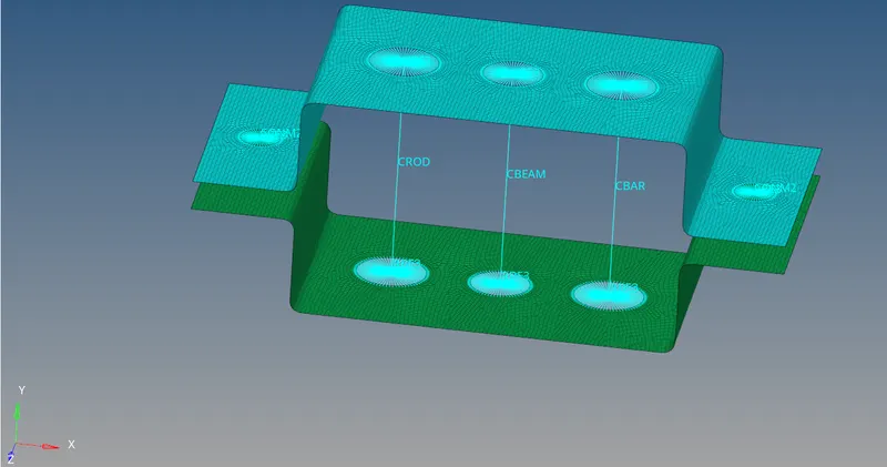
and 1D representation with a detailed view is shown below:
----------------------------------------------------------------------------------------------------------------------------------
Conclusion
The given challenge has been successfully performed, with the creation of ROD, BEAM, and BAR in the Hypermbeam window with the given parameters.