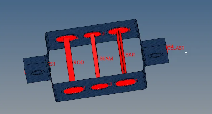
CREATION OF 1D ELEMENTS, BEAMS ON A PARALLEL BRACKET BY USING HYPERMESH
AIM :
To creating an 1D elements such as bar, beam, rod & Spring and also creating a element links such as RBE2 & RBE3 and then Creating an beams with given cross section such as box, I & Cross. All should be done in Hyperworks software.
OBJECTIVES :
1) Creating a RBE2 & RBE3 links as per respective place at where a,b,c,d & e on that given component and then creating spring element at where reference 'f'.
2) Creating the BOX, I & CROSS cross section from Hyperview.
3) Creating the rod element with providing only translation dof and assigning cross section is BOX.
4) Creating the beam element with providing all possible dof and asssigning cross section is I.
5) Creating the bar element with providing only x & y translation dof and assigning cross section is CROSS.
6) Applying the mass magnitude at where place of 'd & e' on which independent node of RBE2 link.
FLOW OF CONTENT :
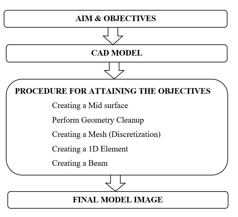
CAD MODEL IMAGE :
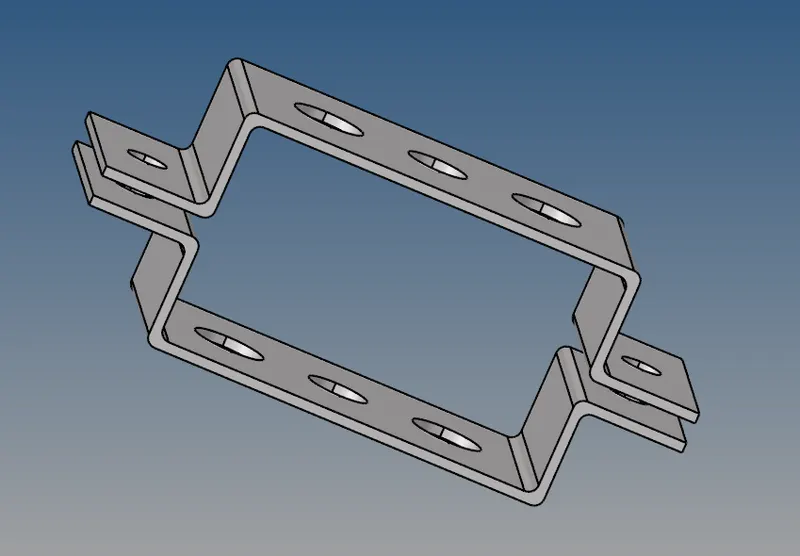
1) This is the CAD model for which importing into hyperworks software by using import geometry option. Model file format type is IGES, so to change into iges file type before importing the model. After importing the file, a model looks like an below image.
2) Assuming the annotations for referance on each holes like 'a, b, c, d, e & f'.
3) Delete the solid, then model surface only visible from graphics area.
PROCEDURE FOR ATTAINING THE OBJECTIVES :
Creating a Midsurface :
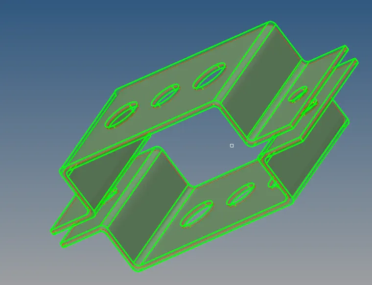
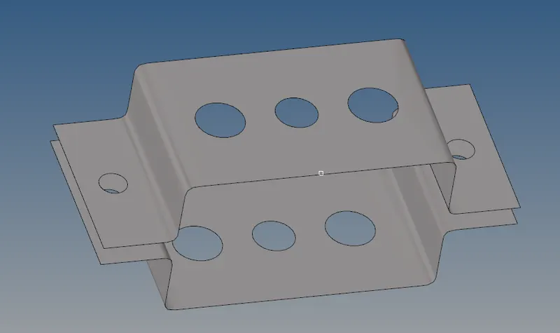
1) A midsurface creates at where between two surfaces, it helps to minimize the calculating time, storage space and gives better solutions.
2) By extracting the midsurface from surface model by using " Auto midsurface" because cross section is same at which throughout the bracket. If a cross section seems to be change, better do some changes on "Extraction Option"
Perform Geometry Cleanup :
1) Geometry cleanup is also called as topology cleanup. If surface have any pin holes, fillets & any editable area throughout the model, by finding both automatically as well as manually. By default we have a automatic option called "Auto Cleanup" and for manually we have some useful panel called "Quick edit, Edge edit and Point edit".
i) Geometry cleanup by Auto Cleanup panel :
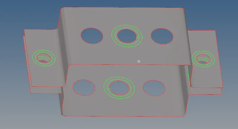
1) By using "Auto Cleanup" panel to perform an automatic geometry cleanup on which given component, it will automatically capturing the surface fillets, Edge fillets, pin holes and other editable lines or surfaces from the given component.
2) After completion of "Auto cleanup" process, it will shown change required place on particular surface component by default it has shown in different categories such as "Free Edge( it shown in Red colour), Sharped edge ( it shown in Green colour), T - Junction Edge( it shown in Yellow) and Supressed Edge ( it shown in Blue)"
3) From below image, a "auto cleanup" panel had fail to cleanup the given surface component, it had missed the some washer split around the hole and also missed to findout the fillets at where bending region of bracket. So we have to do manually for creating an washer splits for getting proper meshing.
ii) Geometry cleanup by manually :
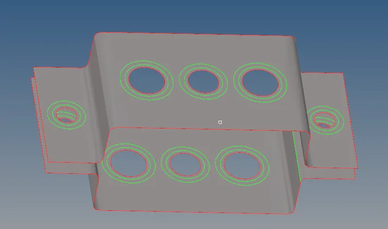
1) Basically, a washer split has help us to create a good orientation mesh and also elements are aligned properly around the hole itselfs. If we couldn't assign any washer split at where any hole, a computer will not finding the hole properly, so that element are crossing the hole free edge.
2) By using " Washer split" Sub panel under "Quick Edge" Panel. To click the "Washer split" with providing the "offset" Value. If click the any hole, a washer split will created by provided corresponding offset distance.
3) After meshing the surfaces to closely looking at where fillets, a mesh didn't cover the fillets. So we draw the line on a fillet surface across the lateral direction, afterwhich a elements are cover the fillet surfaces. This process held under meshing.
Creating a Mesh (Discretization) :
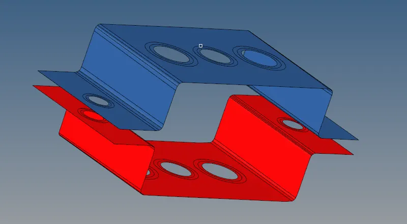
1) To dividing the entire component into infinitesimal control volume, this frame is called Meshing. This process is called Discretization. Each infinitesimal control volume is called element, each element have nodes with respect to ideal shape of the element.
2) By using " Automesh " panel to generate the mesh on a component with element size of 5mm and mixing element of both quadrilateral and triangle. Select the respective surface before execute to "Create" option.
3) By help of washer split, a element quality is good at where around the hole. This is 2D mesh because mesh creates on a mid surface, a mid surface is 2D representation of 3D surface.
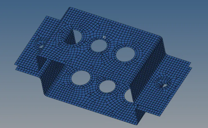
Creating a 1D Elements :
i) Creating the RBE2 & RBE3 element link:
1) We should annotate at each hole for references like a,b,c,d,e & f.
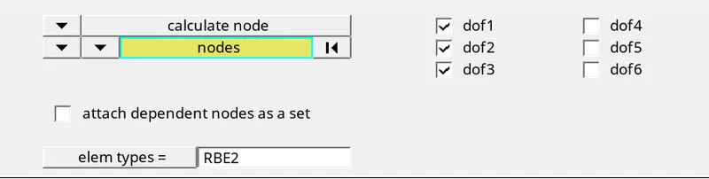
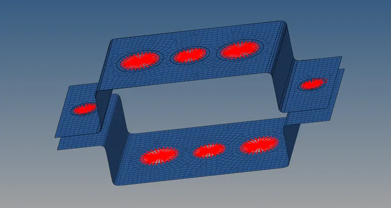
2) We want create a RBE2 link with only translation degree of freedom at where reference place of "a". Selecting the nodes around the hole with selecting the x,y & z dof only and then create. For link have only one independent node. This creation of links in both upper and lower bracket on it.
3) Similarly, Creates the RBE2 link at where reference place of " d & e " with that a mass magnitude is applies on upper bracket corresponds link independent node ratherthan putting on both upper and lower. Because, a mass magnitude always trys to go downwards only.
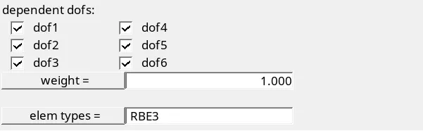
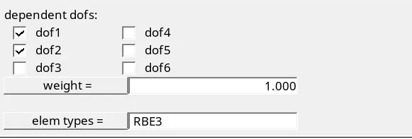
4) Similarly, Creates the RBE3 link at where referance place of "b & c", for "b" degree of freedom is possible in all direction of both translational and rotational and for "c" degree of freedom is possible only x & y translation.
5) These are element links, a links have only one independent node. From which we create the beams.
Element selection for creating link :
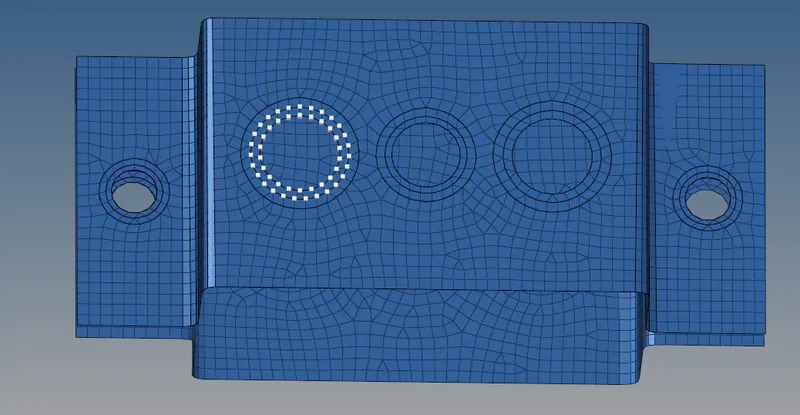
DOF selection for reference 'a' :
DOF selection for referance 'b' :
DOF selection for reference 'c' :
Final Model after assigns all links :
ii) Creating the elements :
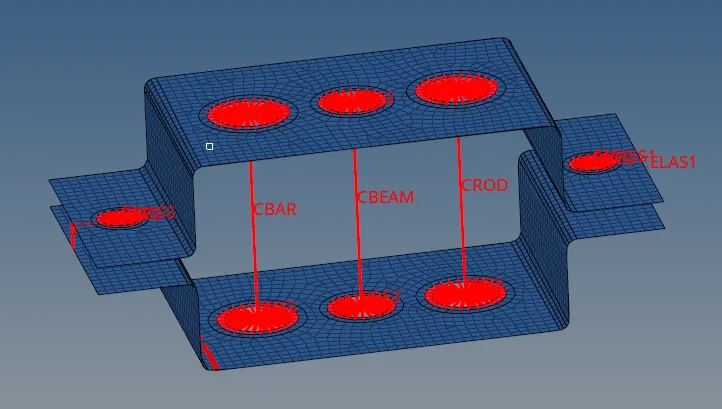
Select the "bar element" option under "1D" sub category from main menu page, select the two independent node from where reference place of "a" with select the element type has "CBAR". Similarly, select the two independent nodes at where reference of "b" with select the "CBEAM" instead of "CBAR"
Select the "rod element" option with select the two independent node from where reference place of "c" with that select the element type has "CROD" and then create. Similarly for which reference place of "f" to create a "Spring element" and also selecting the solver type which as "CELAS1".
Creating a Beam :
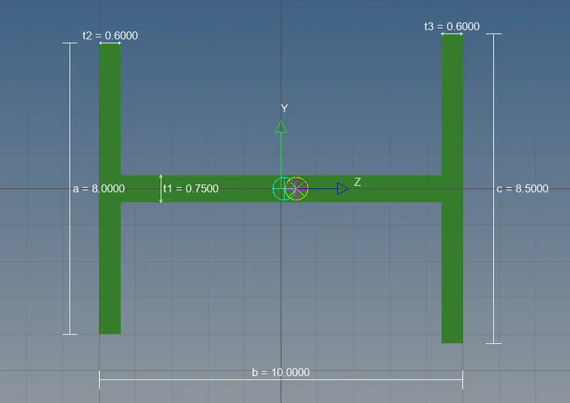
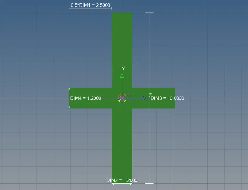
Click the "Hyper Beam" Option from the "Model" main manu page, to create the beam cross section such as " BOX, I, CROSS ".
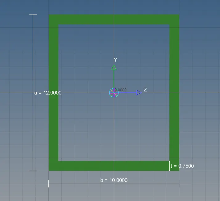
i) For 'BOX' Cross Section :
Dimension, a = 12 mm
Dimension, b = 10 mm
Dimension, c = 0.75 mm
ii) For 'I' Cross section :
Dimension a= 8 mm
Dimension b= 10 mm
Dimension c= 8.5 mm
Thickness t1= 0.75 mm
Thickness t2= 0.6 mm
Thickness t3= 0.6 mm
iii) For 'CROSS' Cross section :
Dimension DIM1= 5 mm
Thickness DIM2= 1.2 mm
Dimension DIM3= 10 mm
Thickness DIM4= 1.2mm
Assigning a properties to beam :
1) Create a property with assigning the respective beam cross section as well as material type and also assigning the respective "CRAD image". We have three different cross sections and three different beam elements.
2) Go to "Rod element" option under which "1D" Main menu page, click the property then assigning the respective beam cross section and also providing the solver type. Similarly assign remaining beam cross section to respective properties.
3) For 3D view of beam, we have change to 1D Detailed element representation from 1D tranditional element representation.
FINAL MODEL IMAGE :
1) In final modal contains two different element link such as RBE2 or Rigids & RBE3, different cross beam are fixed as per given condition.
2) At which reference place of 'f' a spring element is fixed and also mass magnitude is applies on to 'd & e' reference places at where independent node of that link.
3) A blue colour indicates surface component with meshing, a red colour indicates RBE2, RBE3, Beams, Elements and mass magnitude.