Week 4- Challenge
CREATE 1D ELEMENTS ON THE BRACKET MODEL WITH GIVEN CROSS-SECTIONS AND DEGREE OF FREEDOM (DOF).
Objective
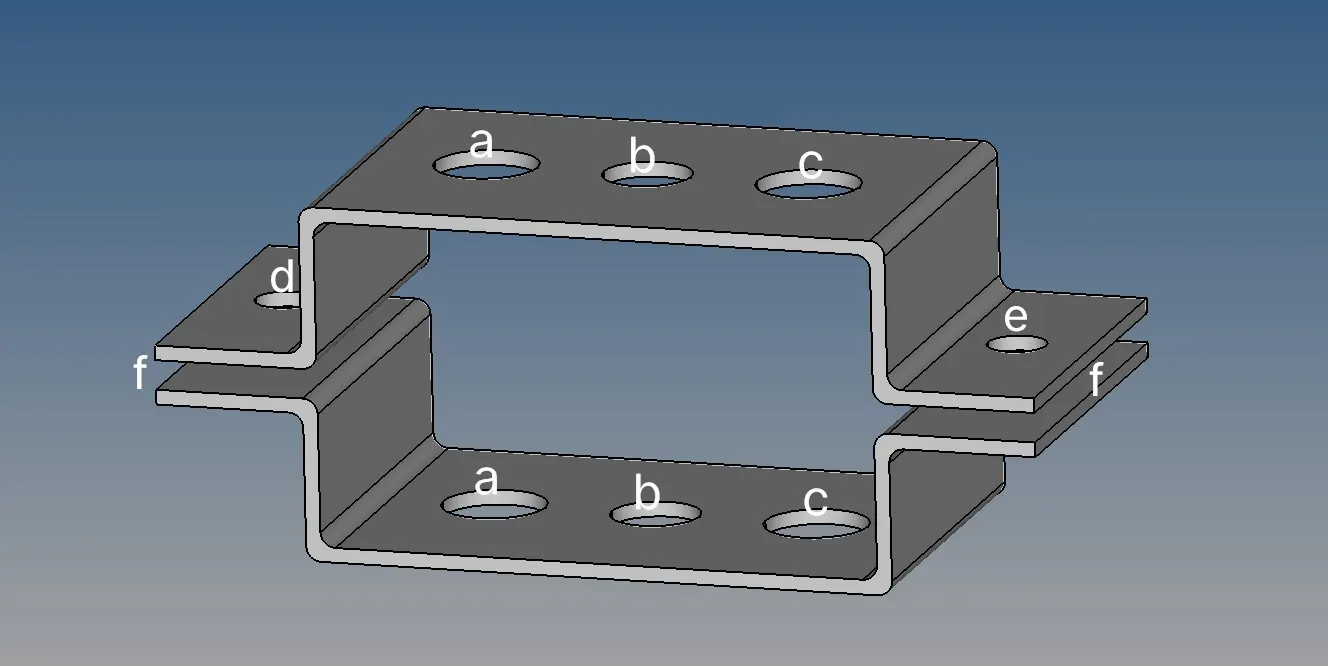
To create 1D elements on the bracket model with given cross section, dimensions and degree of freedom (DOF).
Given data for the 1D element and cross section and DOF.
- Rod element: - with only translational DOF and RBE2 link
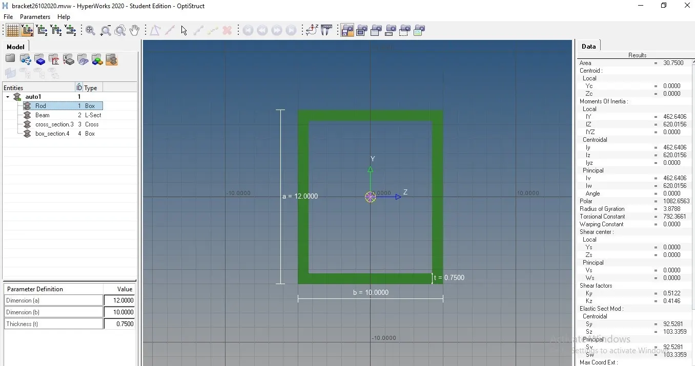
Cross-Section: BOX- Dimension a= 12 mm
Dimension b=10 mm
Thickness t= 0.75 mm
- Beam element: - with all DOF and RBE3 link
Cross-Section: I Section- Dimension a= 8 mm
Dimension b= 10 mm
Dimension c= 8.5 mm
Thickness t1= 0.75 mm
Thickness t2= .6 mm
Thickness t3= .6 mm
- Bar element: - with only x and y DOFs with RBE3 link
Cross-section: CROSS section- Dimension DIM1= 5 mm
Thickness DIM2= 1.2 mm
Dimension DIM3= 10 mm
Thickness DIM4= 1.2mm
- & e. apply the mass of magnitude 10 with RBE2 link
- Join the two components with spring elements
What is 1D element in hyper works?
1D elements created in a space between two or three nodes of a model where beam properties are desired. Bar elements are displayed as a line between two nodes with BAR2 or BAR3 written at the centroid of the element.
Rod elements have property pointers. Rods can translate to CTUBES in Nastran or a C1D2 element in Abacus.
Importing cad model IGES file type.
Here it is important to understand the type of file while importing the cad model. After importing the cad model verify any geometrical errors and unnecessary lines and surfaces present in the model.
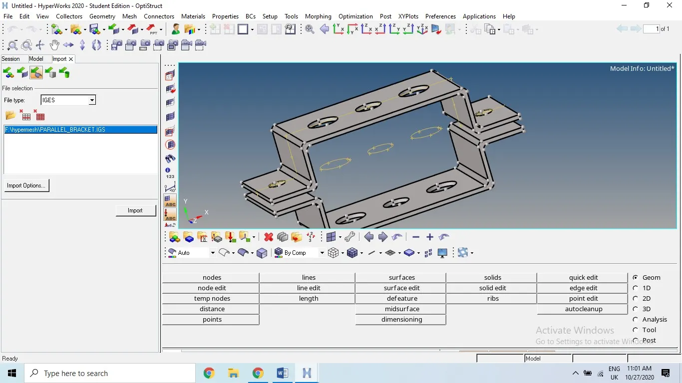
After verifying the model some unnecessary lines are present in the model, we have to delete it.
Tools > delete > lines> delete entity
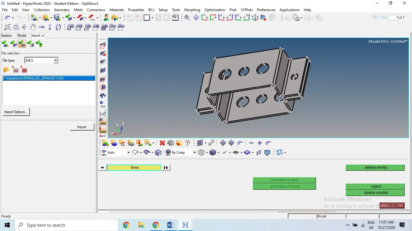
Middle surface: extracted middle surface for the brackets using middle surface command at geometrical tools, geometry > mid-surface >auto mid surface selecting the surface of the model. If the model consist of uniform thickness we go by auto mid surface option whereas thickness is non uniform then we have extract option the list to change the thickness of the each surface.
For non-uniform thickness geometry > mid-surface > extraction option
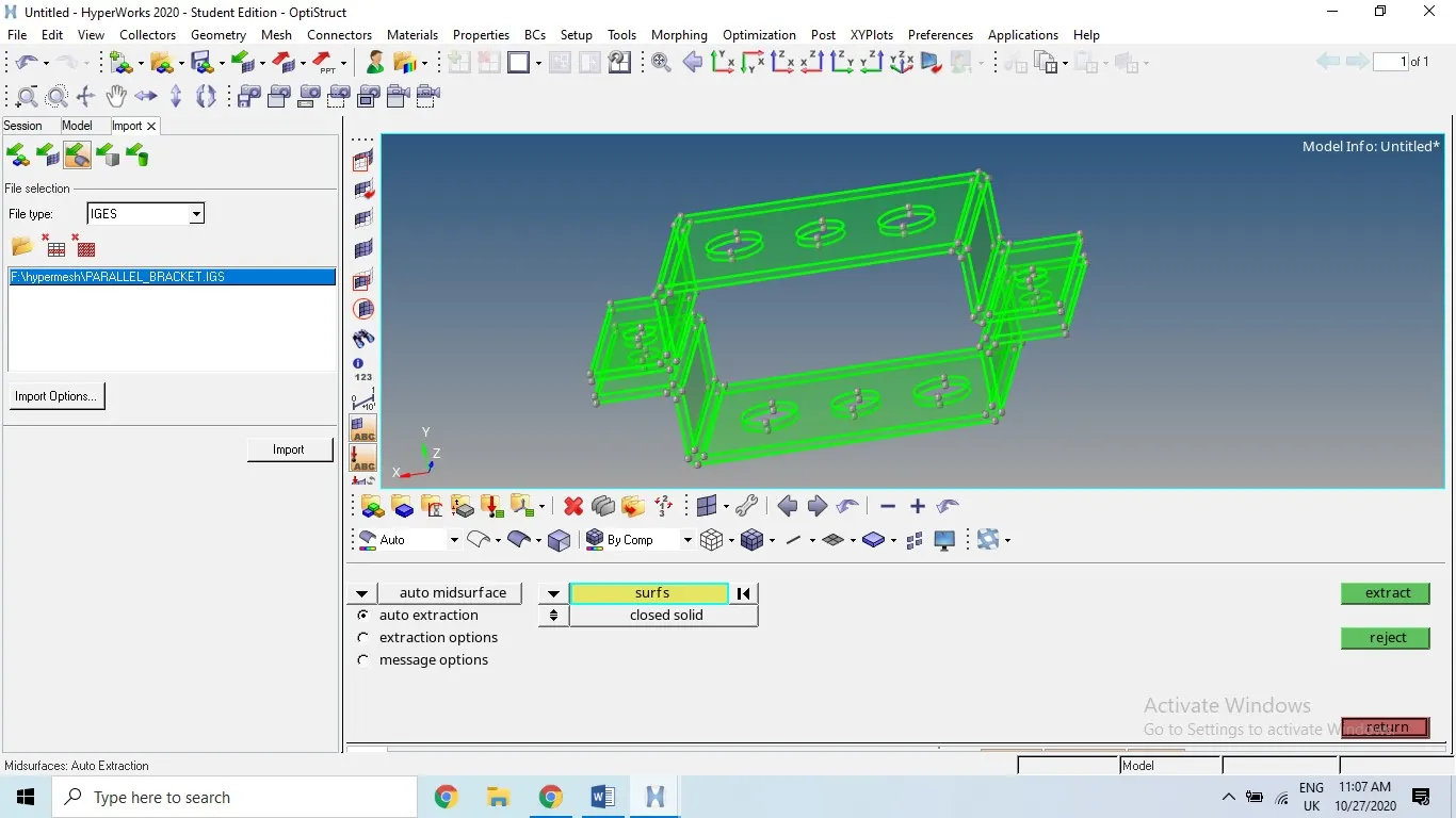
Mid- surface generated here in this image we can see the red line between upper and lower surface of each bracket. In the left side block of the model window. We can delete the parent surfaces of the bracket to get the mid- surface.
After creating the mid-surface, it appear in the component list there we can rename it as bracket one and bracket two ,make sure while assigning the name whether it is bracket one or two before move the mid-surface.
Tools > organize > selecting the bracket we can move the mid surface to anywhere in the left side which name given to the particular mid-surface
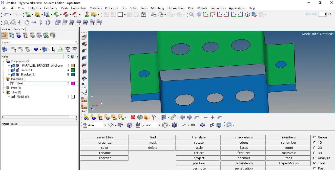
After assigning the mid-surface to bracket one and bracket two we can change the color in the same place by clicking on it

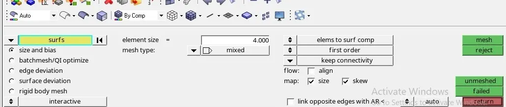
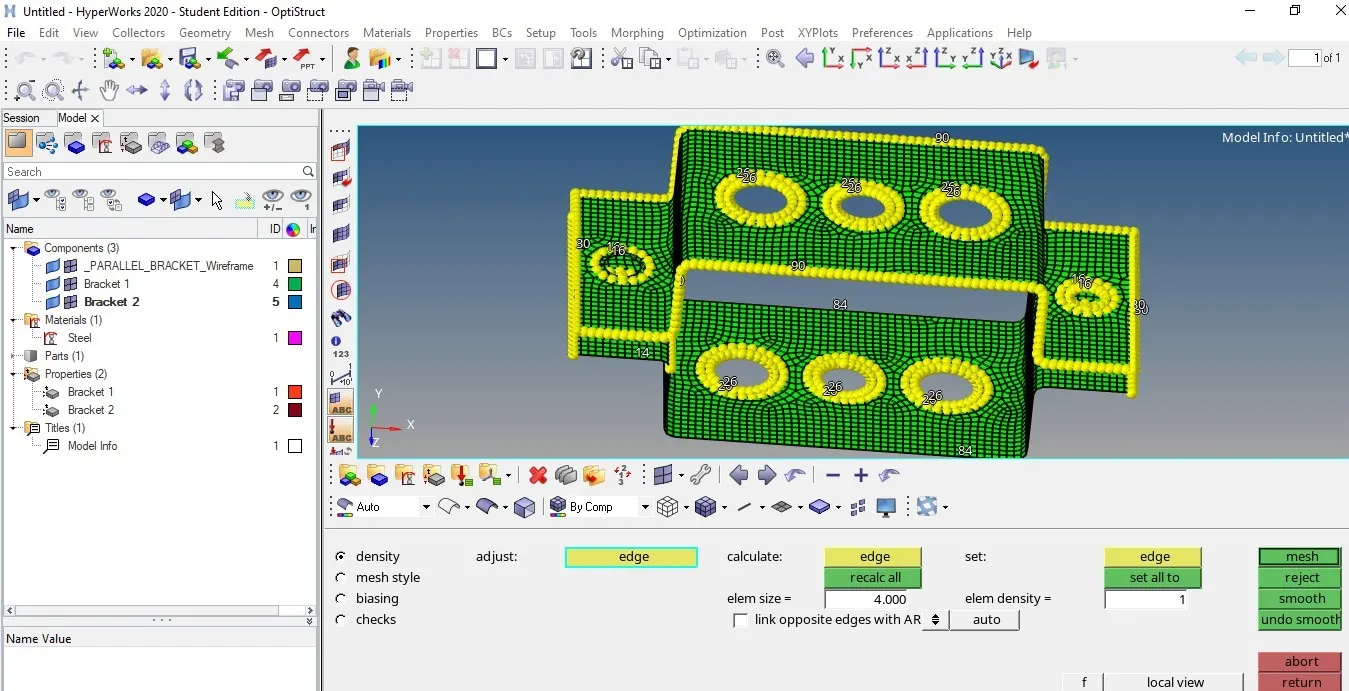
Meshing: 2D surface meshing is done on the bracket after extracting the mid-surface. Element size given here as 4, before going for the meshing we need to create washer cut around the holes. Select the mesh type ass quad or mixed
The bracket is having uniform thickness so we can select auto-mesh option to mesh the bracket at time selecting display all.
2D > auto mesh > selecting element size , and we can change the number of nodes of circular hole and edges by clicking the mouse left and right buttons so that we can make uniform node number on both washer cut and hole edge.
Assigning the material as steel and property of the all 1D elements in the PID along with the cross sections of the 1D elements.
Creating 1D elements
As per the given data we need to create bar, rod and beam 1D elements. These elements helps to bridge the gap between the components and also transfer the loads.
Beam: It is called 1D element used for asymmetrical sections.
Rod: It is used for tensile and compressive
Bar: It is used for symmetrical and simple sections
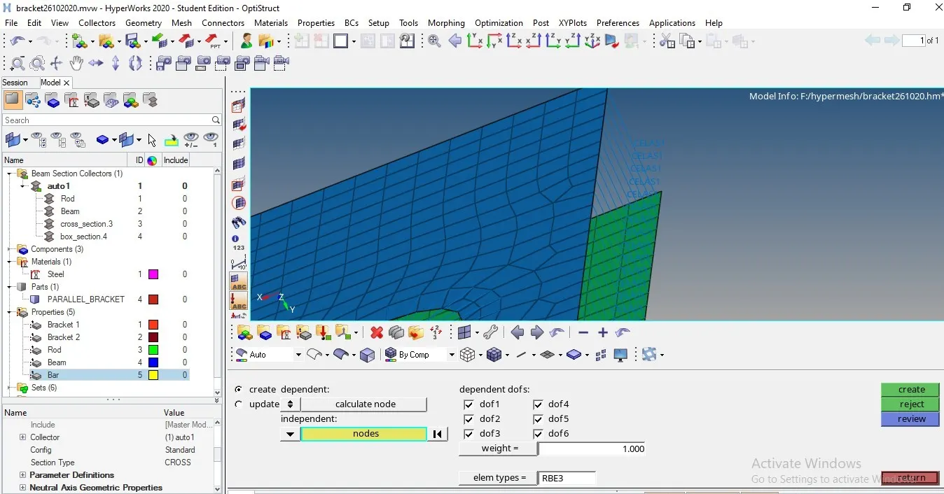
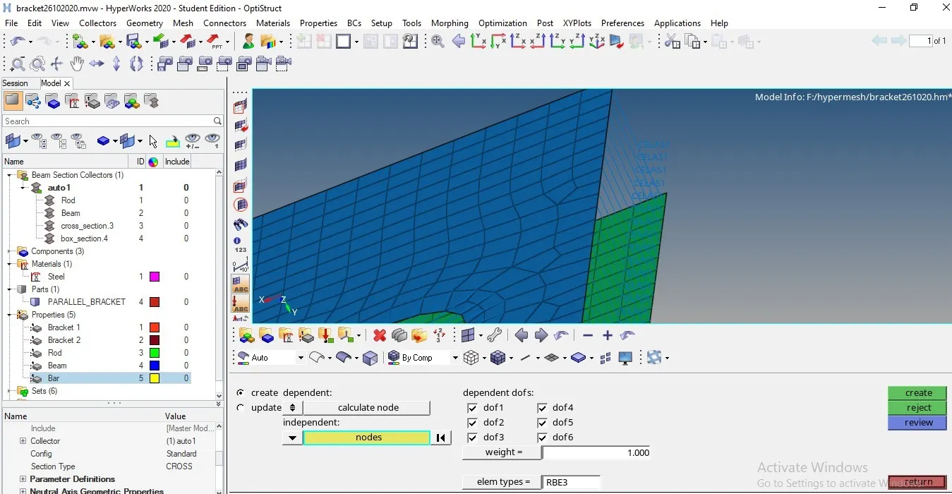
1D >rigid (bar, rbe3, rbe2 and rod)> selecting the element type > create then we update after creating the link elements between the rbe2 and rbe3 or beam or bar element.
DOF: Degree of freedom is number of independent coordinate are constrained in the system. As per the given data of the 1D element we need to select the number degrees of freedom.
Rigid or bars or rbe3 > select the dof based on the link element or position or section.
We can update the link element of any 1D element whenever we want to update it. 1D > selecting the link elements (rigid, rbe3, bars) > select the element type then (for bars orientation of the elements) click on create.
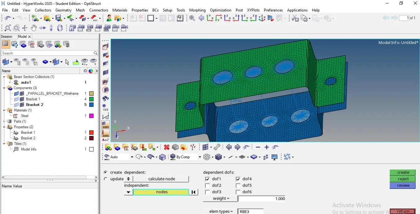
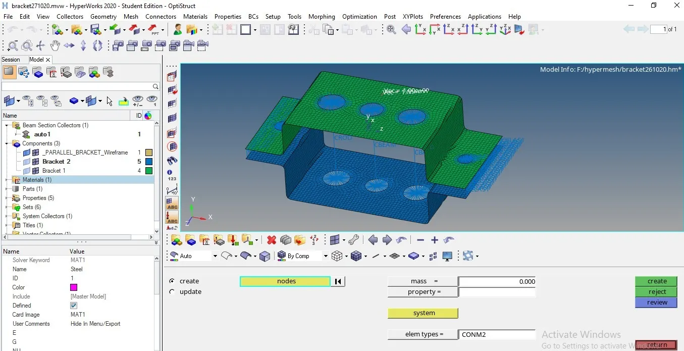
For both side circular hole rbe2 elements are used for both the sides of the bracket and also added mass of the element 1D > mass > select node > element type (CONM1 or CONM2 etc.) >mass (10, 20 …etc.)
The gap between the two brackets are created with spring elements 1D> springs > create or update > node selection > element type (CELAS1) > (property) > create select the node on the bracket1and bracket 2 then automatically connection takes place.
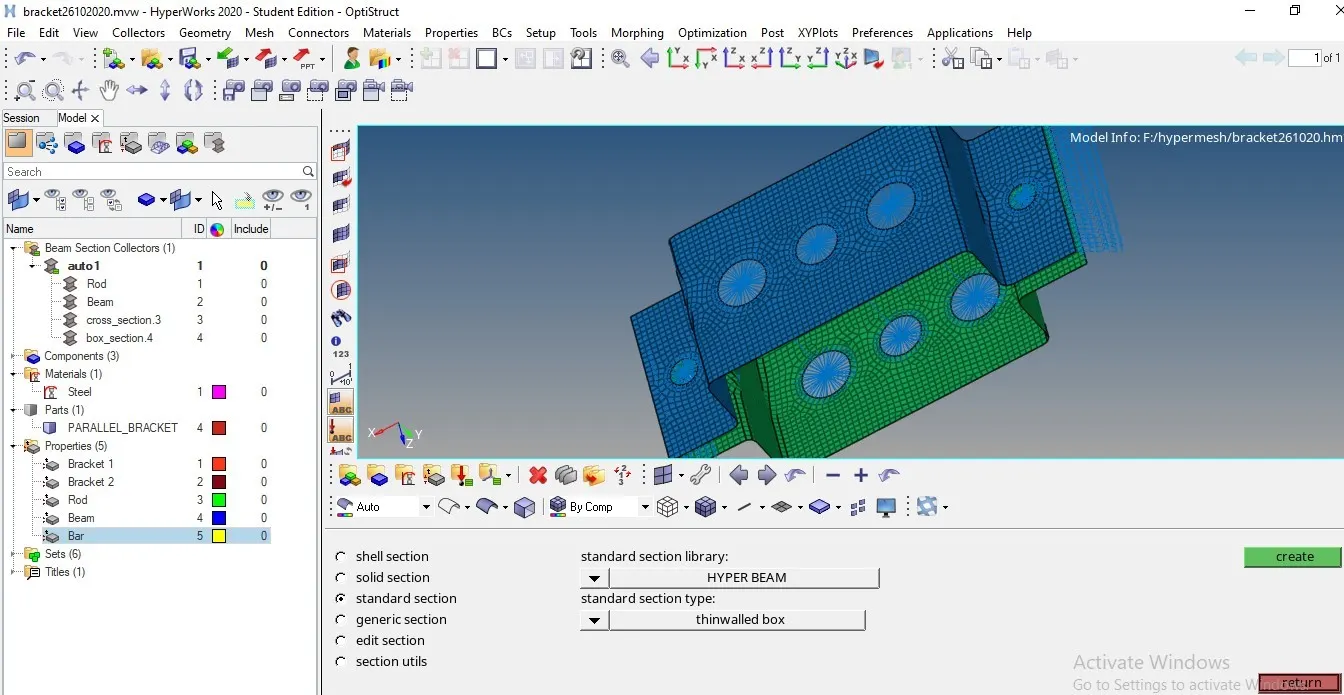
Cross section: each 1D element needs to assign the cross section at hyper beam or optistruct leads to another window where we can create cross section for each link element.
The below image shows the all the connections, each 1D connection consist of cross section like circular , box type , rectangular etc. after creating the cross sections we can update the parameters of the cross secction below as per the given dimension.
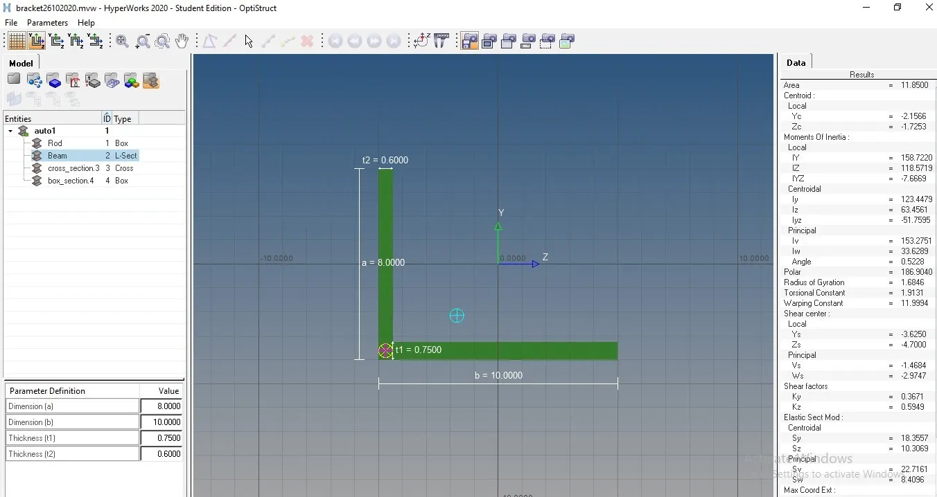
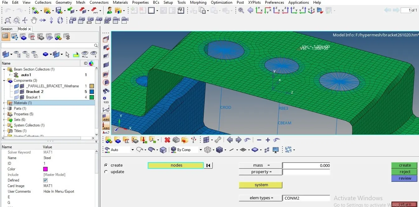
We need to create the bracket material as steel and property Id of the each 1D element as PBAR, PBEAM, and PROD instead PSHELL.
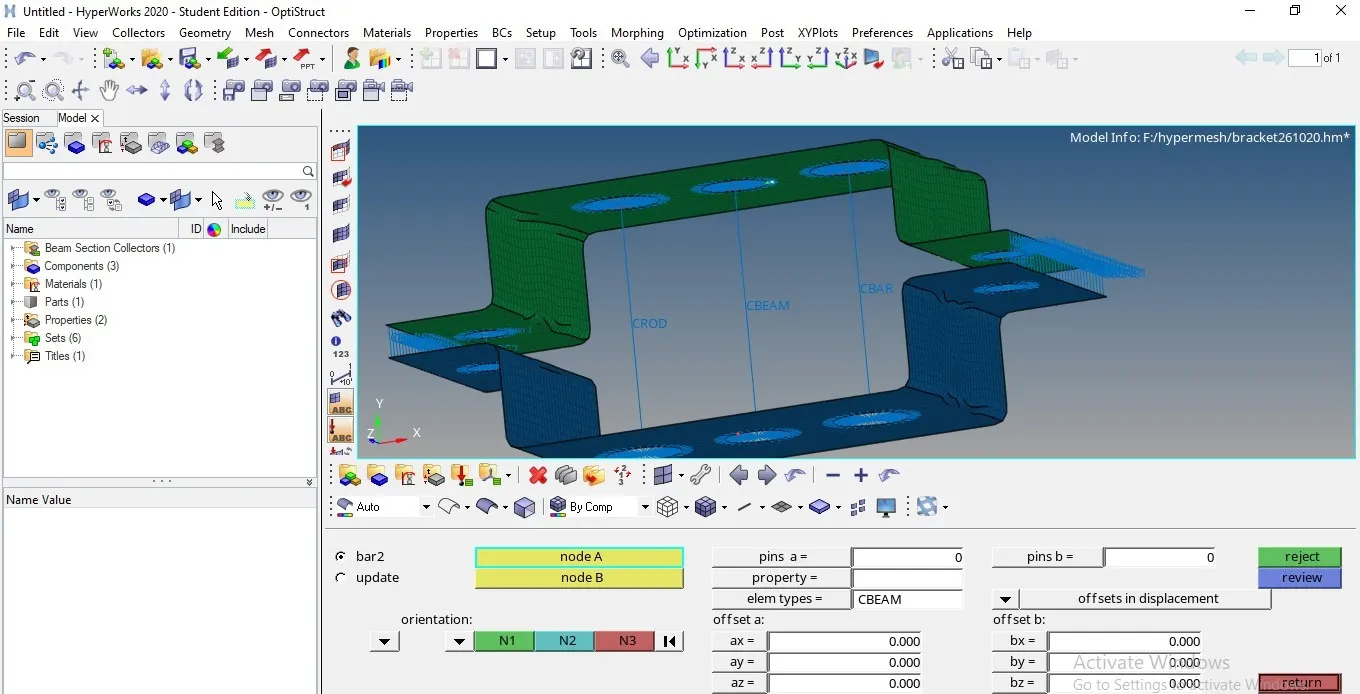
Material : create the material property after creating new material like steel then update the solver grade or card image(MATI1) E,G etc. in the below material details box as shown in the below image.
Below image shows the 1D and 2D detailed elemental representation of brackets and link elements.
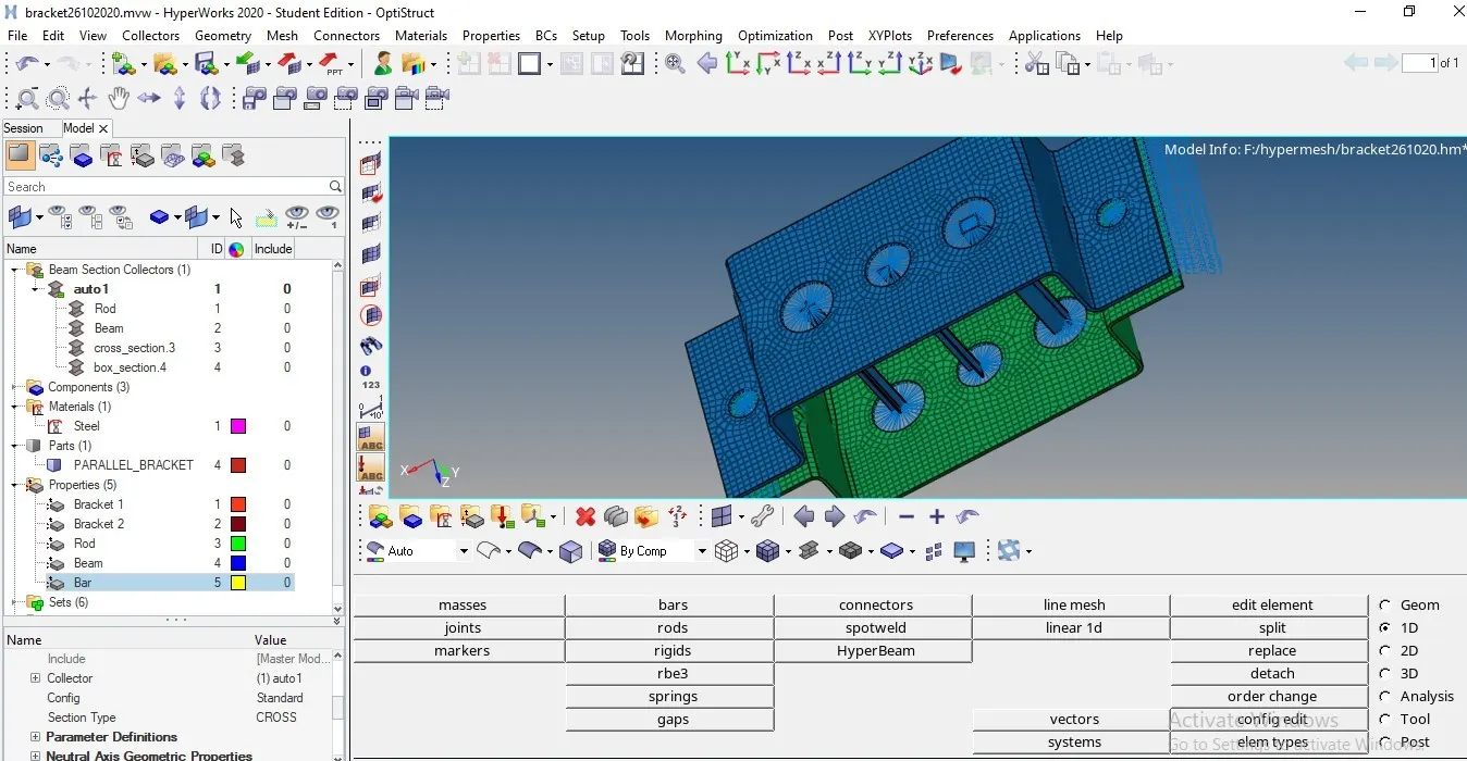
Final image of the bracket after meshing with 1D elements as per the given cross section.
Outcomes
- Learned how to extract mid-surface with uniform and non- uniform type components
- Leaned how to create 1D elements like bar, rod, beam and assigning cross section.
- Creating and updating the material property, part ID of 1D elements.
Conclusion
2D surface Meshing and 1D element connection is done on the bracket as per the cross section specification given data, also mid-surface extracted for both the brackets.
https://drive.google.com/file/d/1MgdnUA8bP-BcUXo31qRjUGhCpqGEiDTj/view?usp=sharing