1D ELEMENT
AIM:The aim is to create a 1D element in a given component with a given crossection and the DOF at the different stated points in the question.
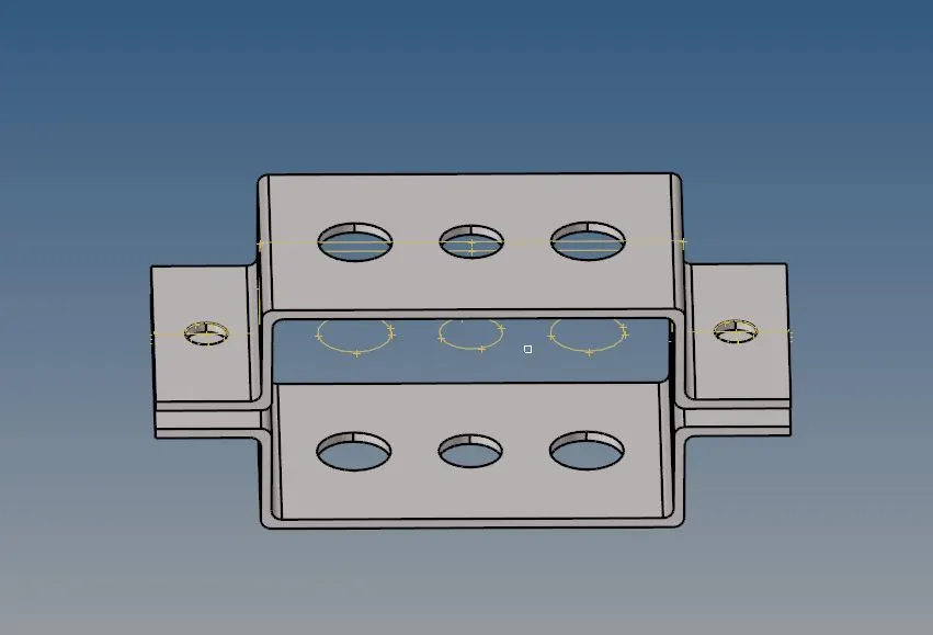
PROCEDURE:(a)The model which we have got for performing the opertion is in IGES file so we need to import it in import geometry and making the file type to be the IGES.The model is stated below:
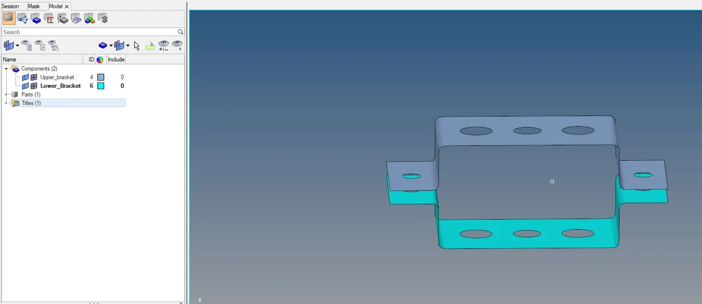
(b)Now in the component we have the 3 default component in which we have got to take the mid surfacing and naming them the Upper Bracket and the lower bracket.We can seggregate the upper and the lower part by using TOOL>ORGANIZE.After having the mid surface we can delete the CAD geometry because it is of no use whatever task are to done is being done in midsurface.
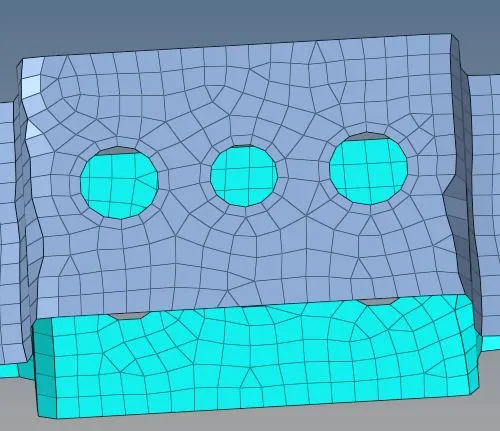
(c)Now we perform the mesh we go to automesh with element size is 8mm before to it we create a washer in a every particular hole given of 5mm then we put it in a mesh.The geometry we have got from it is shown below:

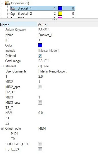
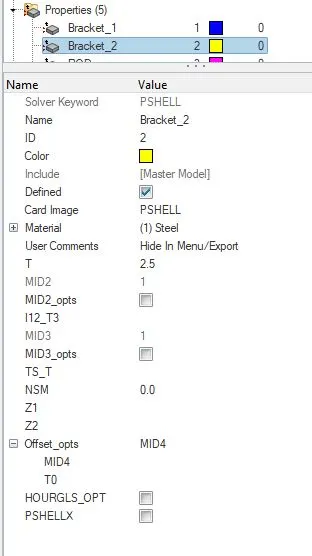
And we have to assign the property as steel for both the brackets 1st one thickness is 2mm and the 2nd one thickness is 2.5mm and the material is assigned as steel which had already been created.
(d)Now we have got to create the ROD ,BEAM,BAR with given parameters stated down:
a. Rod element:- with only translational DOF and RBE2 link
Cross-Section: BOX- Dimension a= 12 mm
dimension b=10 mm
Thickness t= 0.75 mm
b. Beam element:- with all DOF and RBE3 link
Cross-Section: I Section- Dimension a= 8 mm
Dimension b= 10 mm
Dimension c= 8.5 mm
Thickness t1= 0.75 mm
Thickness t2= .6 mm
Thickness t3= .6 mm
c. Bar element:- with only x and y DOFs With RBE3 link
Cross-section: CROSS section- Dimension DIM1= 5 mm
Thickness DIM2= 1.2 mm
Dimension DIM3= 10 mm
Thickness DIM4= 1.2mm
For that we have to give RBE2 and RBE3 connection in those particular section.Let's begin with ROD element first we give the connection in a order of asking :

Now for BEAM connections are stated below:

Now the BAR element:

(e)Now after giving the connection of RBE2 and RBE3 now we move to 1D>HYPERBEAM AND creating the BOX for ROD,I-SECTION for BEAM and CROSS SECTION for the BAR with a given criterion metioned, more precisely showing below:
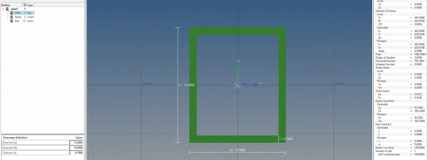
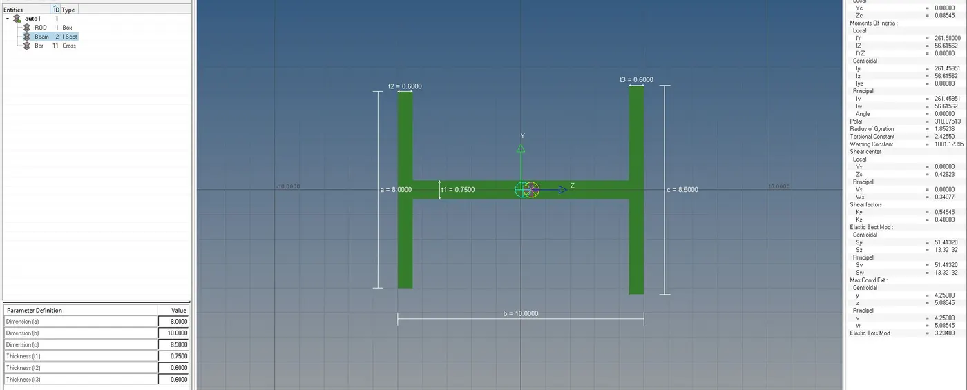
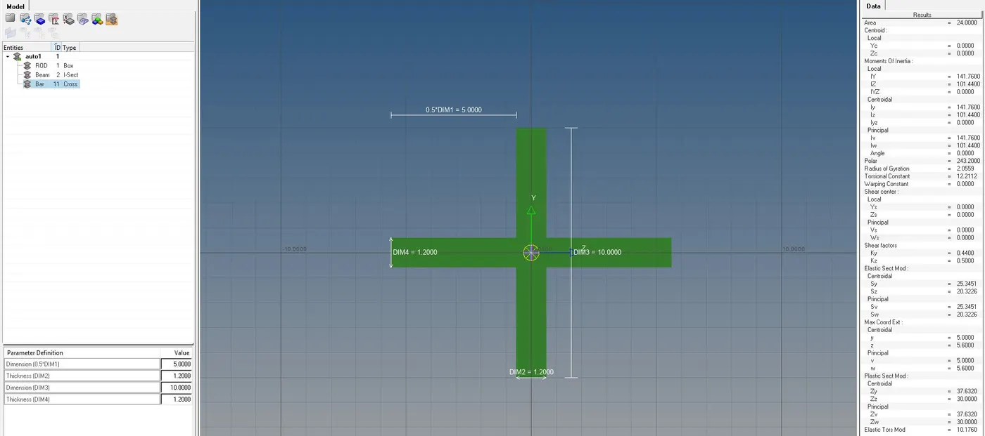
(e)After this we need to assign different property for 3 of them separately and then we go to 1D>Bars and 1D>rods and assign the respective in it one by one as shown in the image:
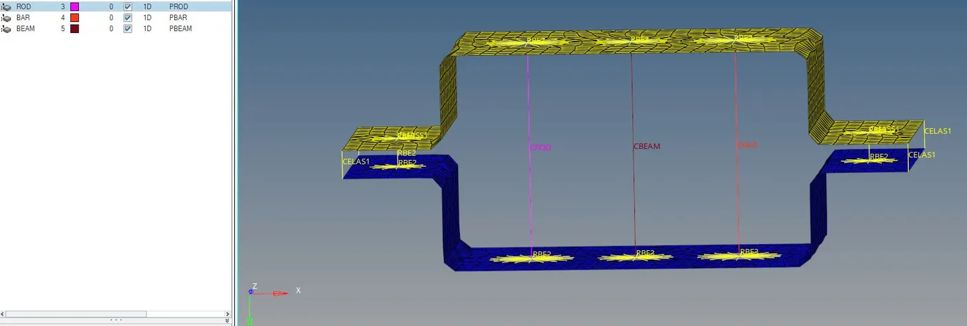
(f)Then at last we have 2 things left those are to assign mass and spring at the given location ,for mass 1D>MASS and given the mass as 10 then we assign a point and the element type could be taken anything or specificaly told to us here we choose CMASS.Before we assign the RBE2 connection before giving the mass.
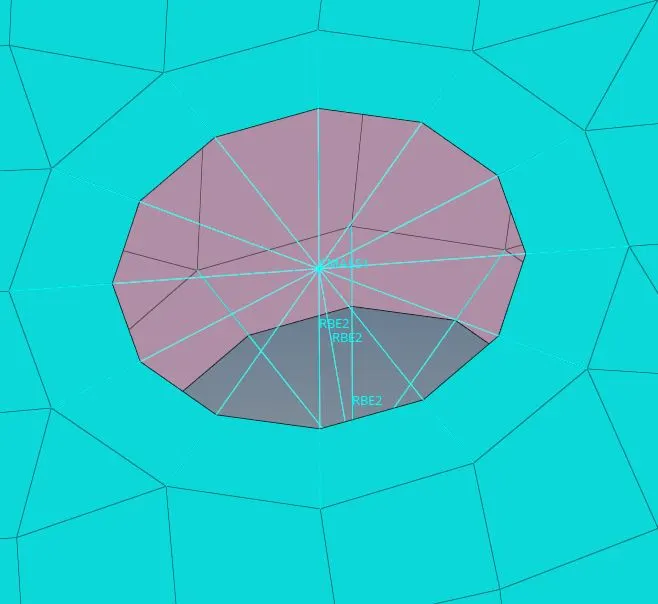
Likewise we assign the spring at the 4 corners of it 1D>Springs.
Now after completion of all the task model looks something shown below:
We are choosing the 1D detailed element representation alog with 2D detailed element representation.
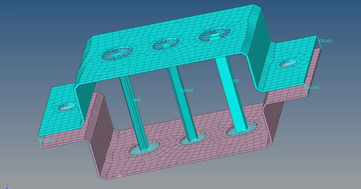
CONCLUSION:(I)Here we have got to know about all the 1D elements working,uses and there connections which includes the spring ,rbe2 and rbe3 along with the uses of hyperbeam to get a different structure needed.
(II)Actually Rod is a member which is Circular In cross section. But Bar can be of any cross section like rectangular bar, square bar, I- section bas etc. But a Beam Can be of any cross section either circular or any other. The main difference between Bar/Rod & Beam is in the basis of loading conditions.