Week 4- Challenge
CREATING 1D ELEMENTS ON THE GIVEN COMPONENT WITH GIVEN CROSS-SECTION AND FREEDOM
OBJECTIVE:
To create 1D elements on the given component (parallel brackets) with given Cross-section and DOF (Degree of Freedom).
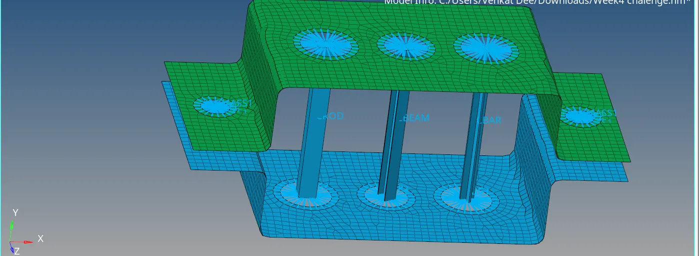
Given CAD model image: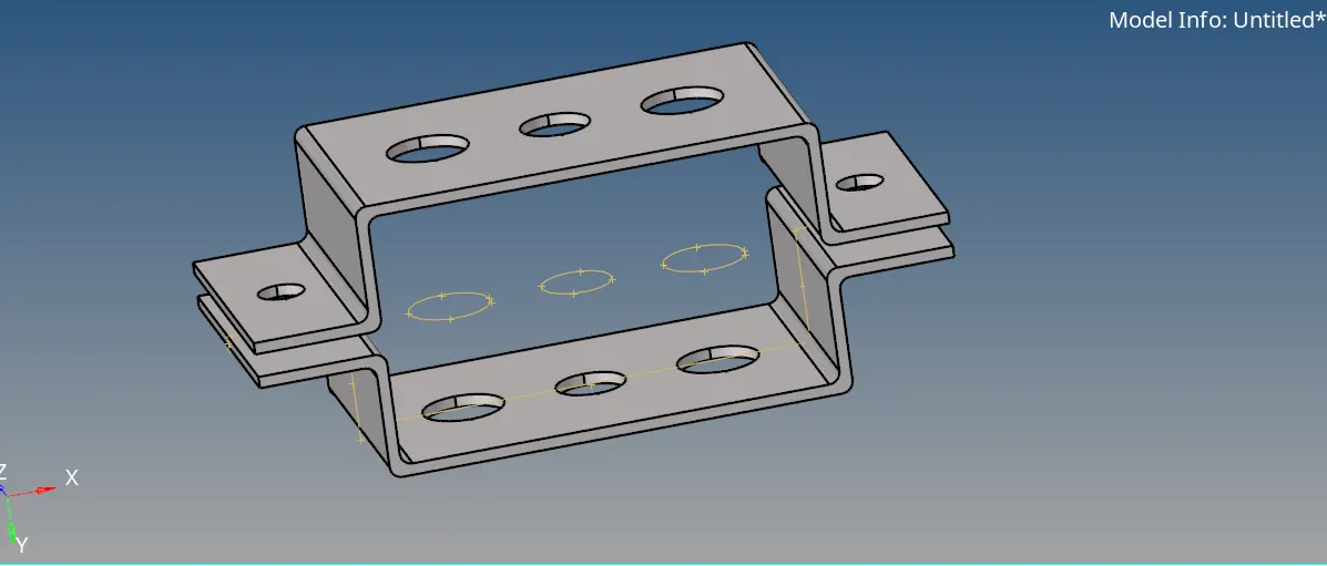
Theory:
1.Hyperworks: Hyperworks is a complete package solutions of CAE offered by ALTAIR Engineering. The package includes pre-procesor, solver, post-processor. Hyperworks package includes softwares like Hypermesh, Hyperview, Hypergraph, Hyperextrude, Hyperform, OptiStruct, Radioss, FEKO, Simlab etc..
2.Hypermesh: Hypermesh is a meshing software which comes along with the other softwares of Hyperworks. It's prime function is meshing. Meshing is an importants process in Finate Element Method.
3.FEA(Finate Element Analysis): FEA is a tool to simulate the physical phenomena using mathematical numerical techniques by discretizing into small elements.
4.Meshing: The process of discretization of elements to solve a set of governing equations throughout the computational domain.
5.RBE2 & RBE3: RBE2 elements are also known as Rigids which have infinite stiffness. RBE2 element is a rigid element with one independent node & multiple dependent nodes. The load distribution is uniform in RBE2 elements. In RBE2, the load distribution is not uniform and the load distribution depends on the distance from the load.
Given Specifications
a. Rod element:- with only translational DOF and RBE2 link
Cross-Section: BOX- Dimension a= 12 mm
dimension b=10 mm
Thickness t= 0.75 mm
b. Beam element:- with all DOF and RBE3 link
Cross-Section: I Section- Dimension a= 8 mm
Dimension b= 10 mm
Dimension c= 8.5 mm
Thickness t1= 0.75 mm
Thickness t2= .6 mm
Thickness t3= .6 mm
c. Bar element:- with only x and y DOFs With RBE3 link
Cross-section: CROSS section- Dimension DIM1= 5 mm
Thickness DIM2= 1.2 mm
Dimension DIM3= 10 mm
Thickness DIM4= 1.2mm
d. & e. apply the mass of magnitude 10 with RBE2 link
f. Join the two components with Spring elements
Procedure:
Importing the Geometry
Goto FILE-Import-Geometry-select file(parallel brackets)-IMPORT.
EXTRACTING MIDSURFACE:
Step1: To extract the midsurface goto Geometry-Midsurface-select surface to be extacted-Extract. Rename the midsurface as Bracket1.
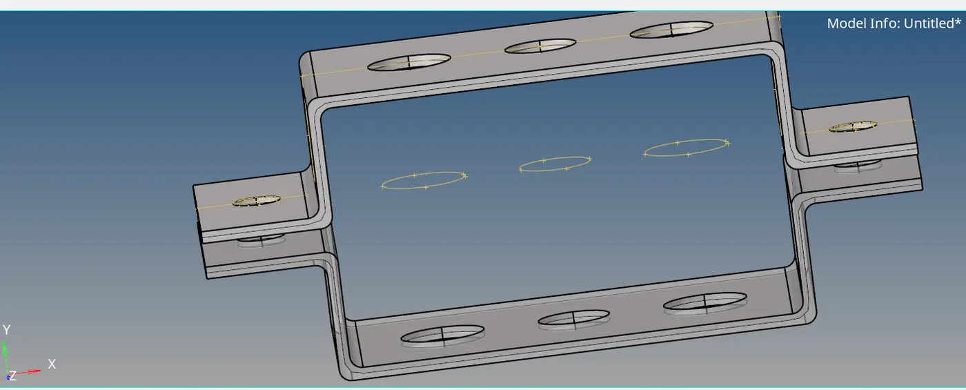
Step2: Create a new component by Right click-component-create. Rename it as Bracket2.
Delete the solid part and wireframe.
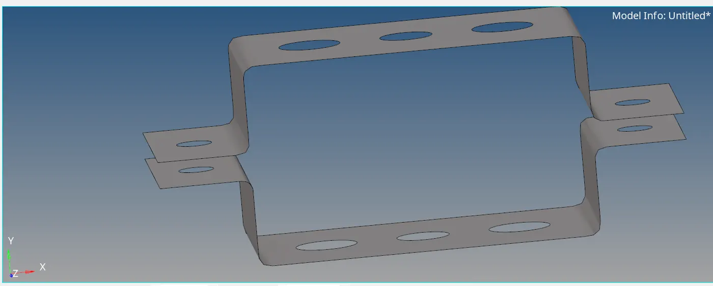
Step3: Moving the Midsurafce to Bracket2.
To move the surface Tool-Organise-select Surface-select Bracket2 at dest component-Move.
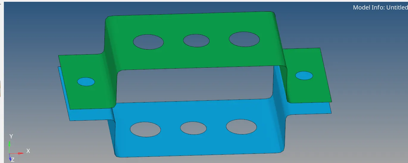
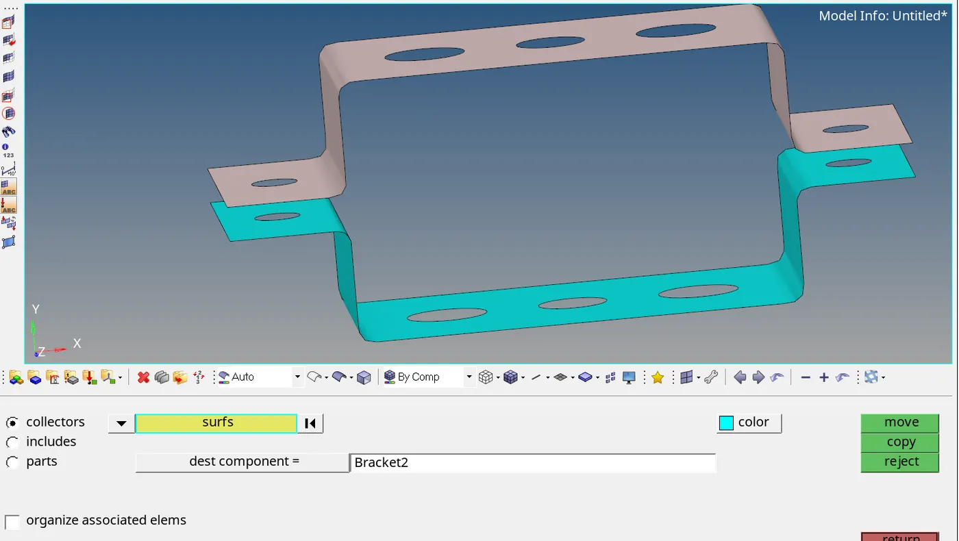 Changing the colour of the Brackets.
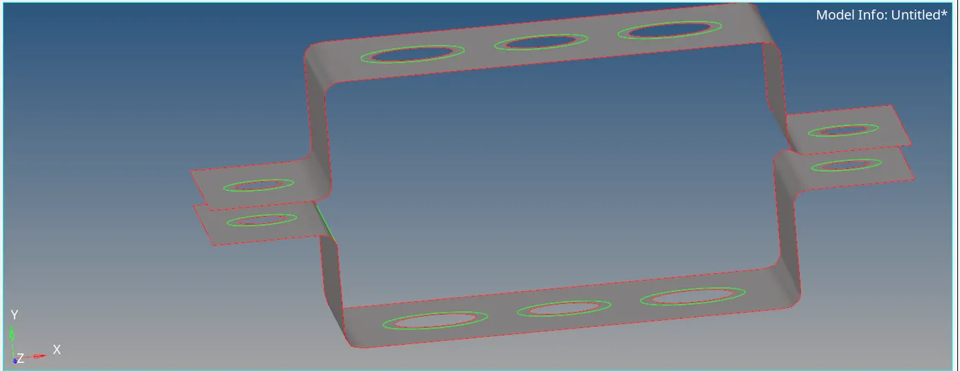
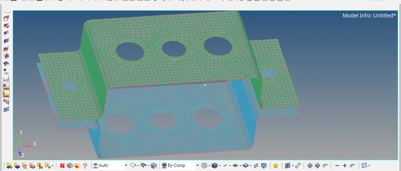
MESHING THE BRACKETS:
Step1: Create the washer split before meshing. To create washer split goto Quick edit-Washer split-Offset value as 5-select Lines.
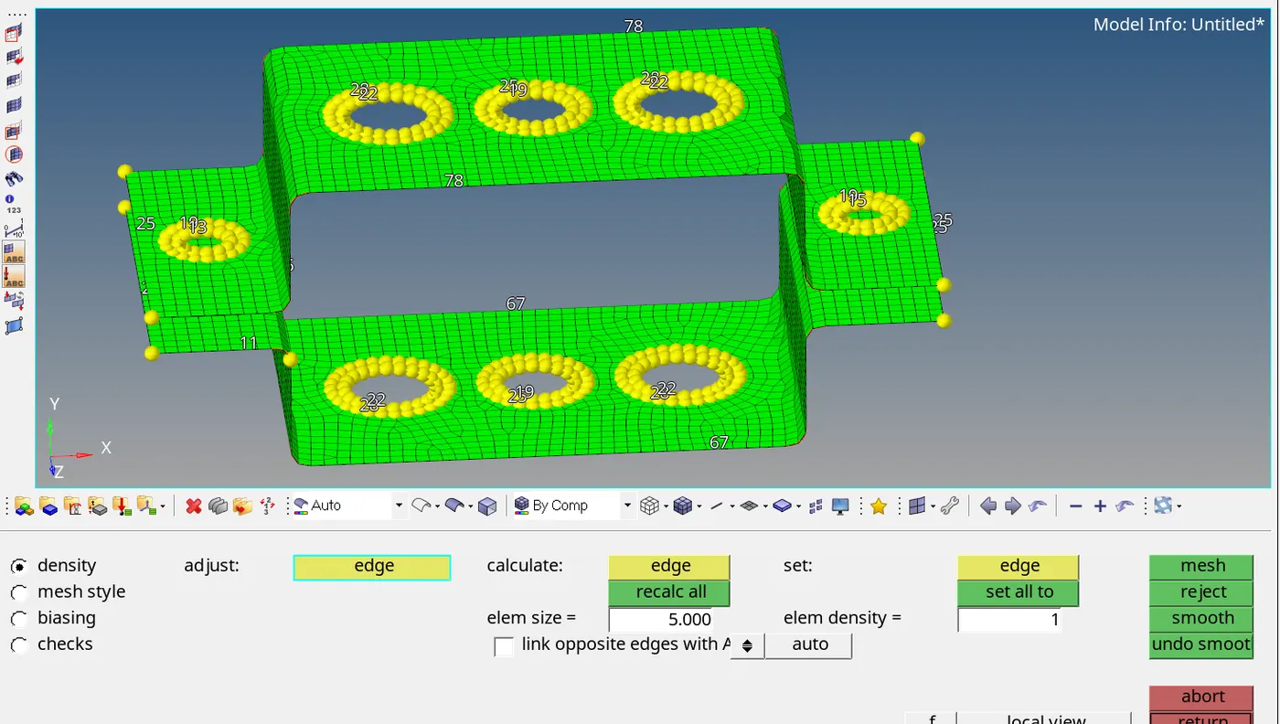
Step2:Meshing of Brackets. To mesh 2D-Automesh-select Surfaces-Element size5-Mesh.
CREATING MATERIAL & PROPERTIES
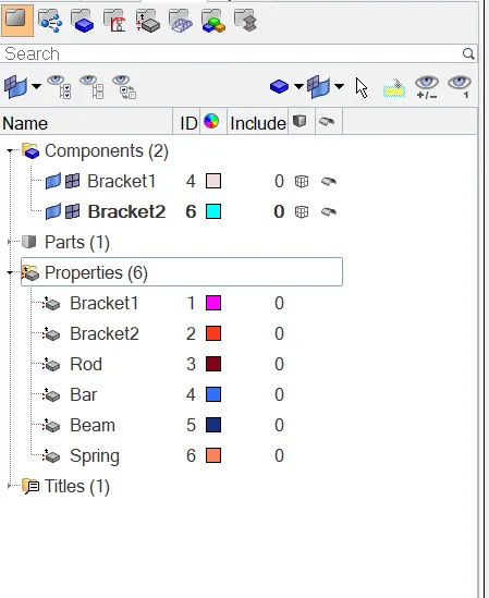
In model tree, Right click-create-material. Give material name as Steel.
To create Property, Right click-Property.
Create property for Bracket1, Bracket2, Bar, Rod, Beam and Spring.
Give Card Image for every property as mentioned below
Property Brand Image
Bracket1 PSHELL
Bracket2 PSHELL
BAR PBAR
ROD PROD
BEAM PBEAM
SPRING PBUSH
CREATING ROD, BAR, BEAM AND MASS ELEMENTS
1.Creating Rod
Step1: Create RBE2 link.
1D-Rigids-select nodes-Uncheck dof1, dof2, dof3 (translational dof)-Create.
Step2: Create Rod.
1D-rods(select the nodes)-Give property(rod).
2.Creating Beam
Step1: Create RBE3 link.
1D-RBE3-select nodes-uncheck all the dof-Create.
Step2: Create Beam.
1D-bar(select nodes)-Give property(Beam)-element type(CBeam)-Give orientation.
3. Creating Bar
Step1: Create RBE3 link.
1D-RBE3-select nodes-uncheck dof1, dof2, dof4, dof5 (x and y dofs).
Step2: Create Bar.
1D-bar(select nodes)-Give property(Bar)-element type(CBar)-Give orientation.
4. Creating Masses
Step1: Create RBE2 link.
1D-Rigids-select nodes-create.
Step2: Create Masses.
1D-masses-give magnitude 10-element type(CMASS1)-Give property Bracket1 or Bracket2-create.
5. Creating Springs
1D-springs-select nodes-Give property(spring)-element type(CELAS1)
CREATING CROSS-SECTION
1D-Hyperbeam-Standard selection-HYPERBEAM-create.
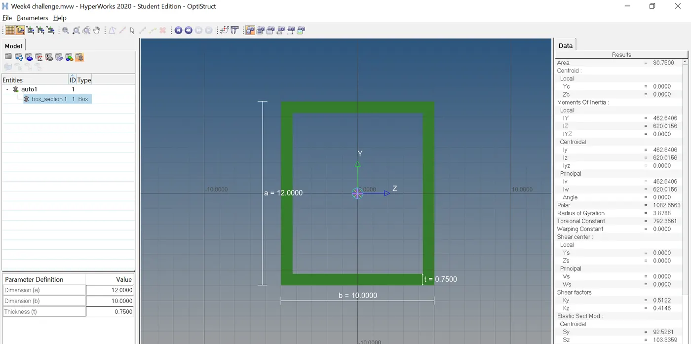
1.Creating Box cross-section
Dimension a= 12 mm
Dimension b=10 mm
Thickness t= 0.75 mm
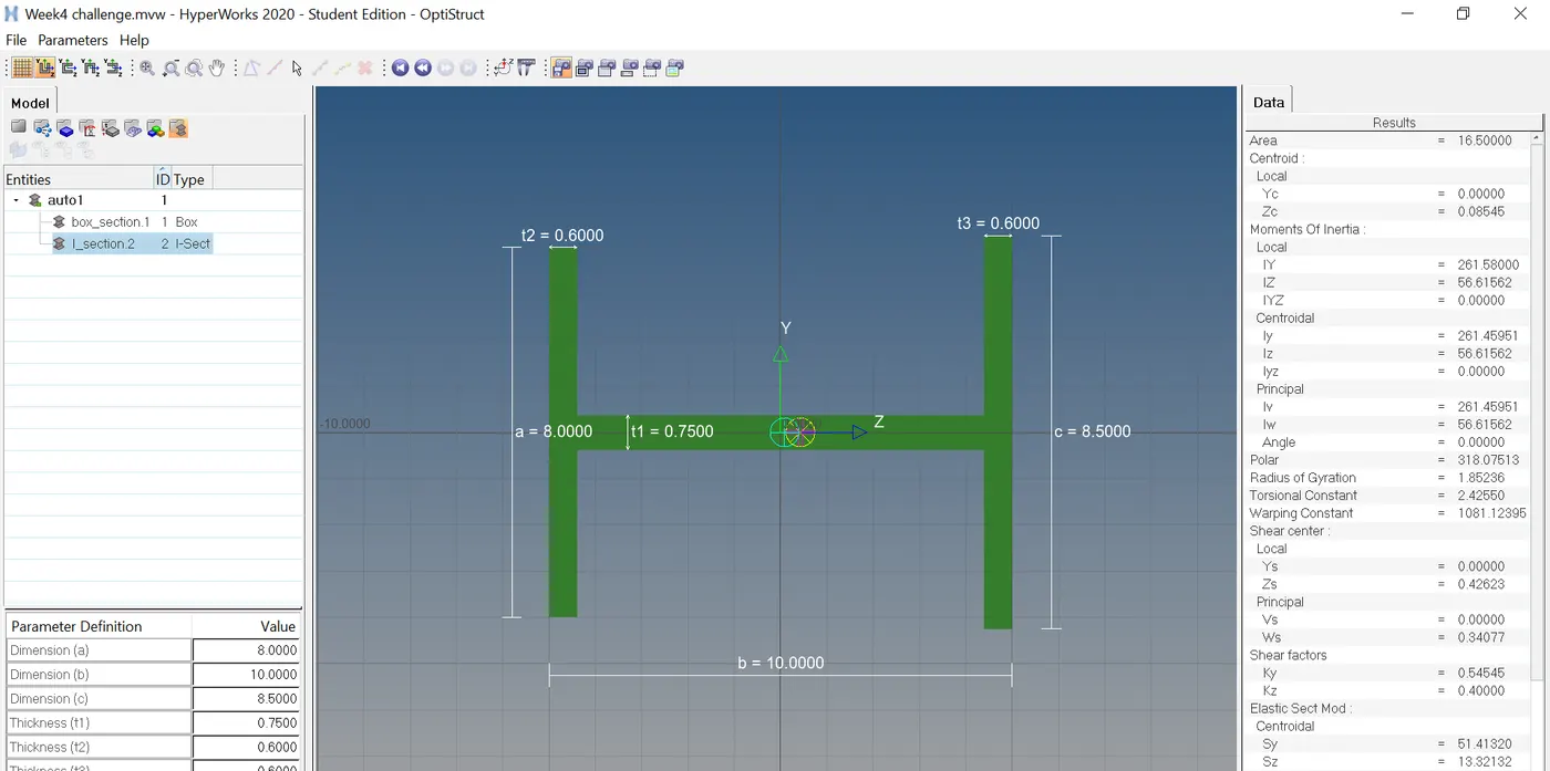
2.Creating I section
Dimension a= 8 mm
Dimension b= 10 mm
Dimension c= 8.5 mm
Thickness t1= 0.75 mm
Thickness t2= .6 mm
Thickness t3= .6 mm
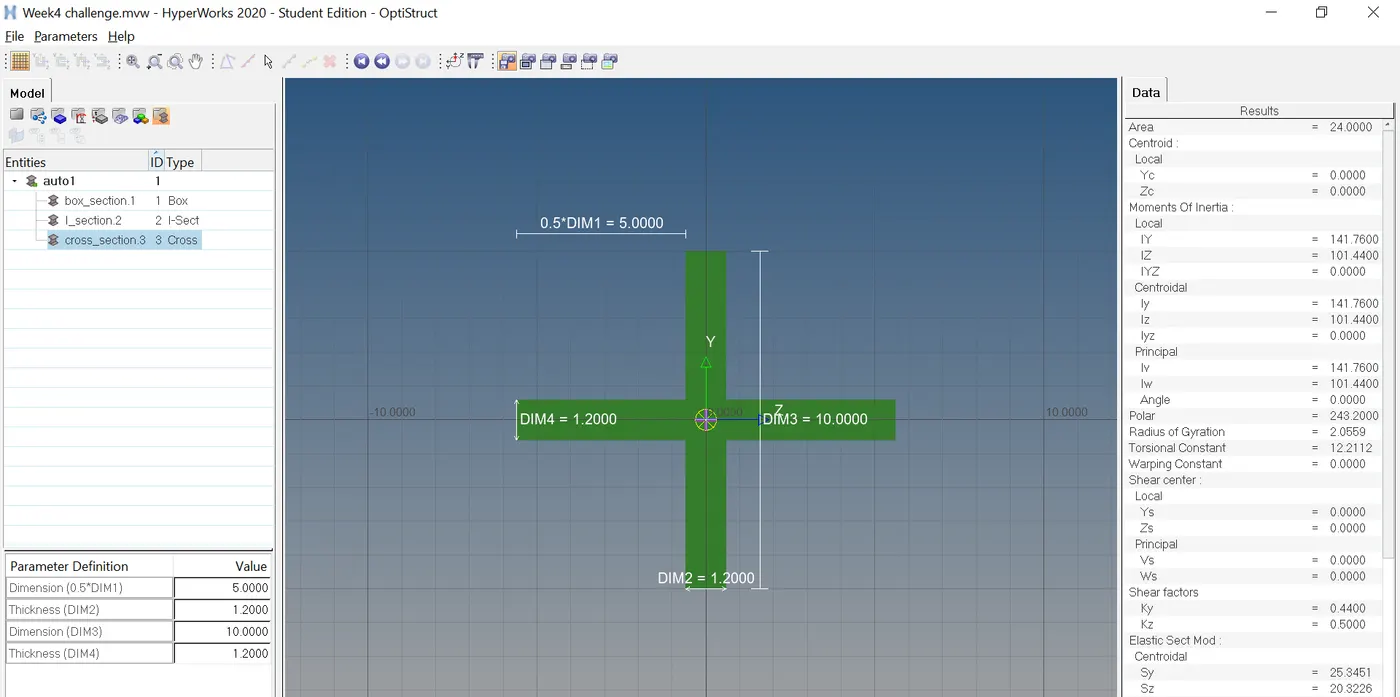
3.Creating Cross cross-section
Dimension DIM1= 5 mm
Thickness DIM2= 1.2 mm
Dimension DIM3= 10 mm
Thickness DIM4= 1.2mm
Assigning cross-sections to the components:
Select the component-Specify the correct beam section.
RESULTS:
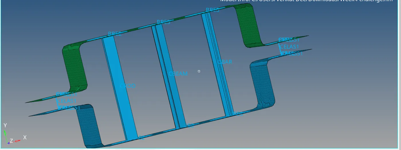
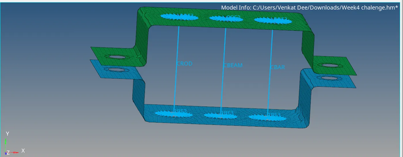
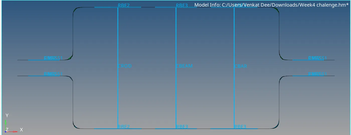
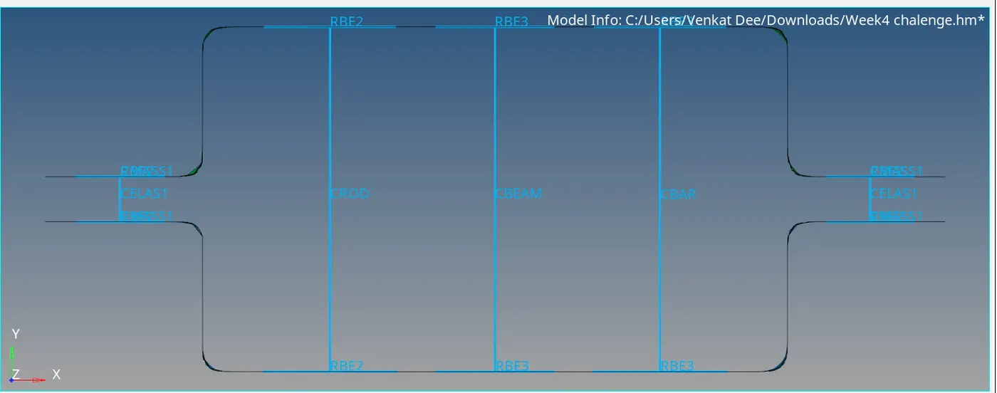
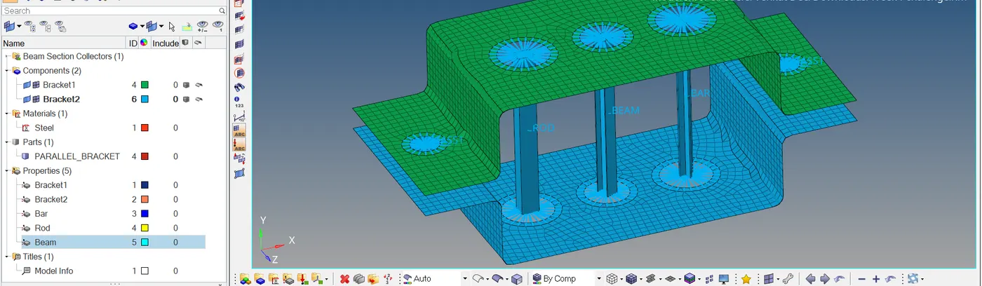
The Geometry was imported, created the midsurface and meshed it. Created 1D elements (Bar, Rod, Beam, Masses and Springs) to the given component.
Final model image