Week 4- Challenge
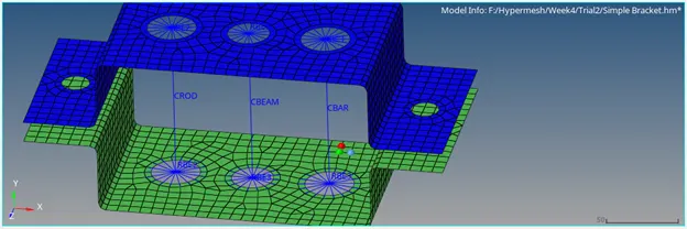
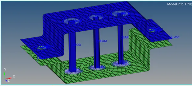
Objective: To add 1D elements (Rod, Beam, Bar, Mass and Spring) of different cross section (Thinwalled box, I section and Cross) to the given component using RBE2 and RBE3 link at given positions (a, b, c, d&e and f as shown in the given image).
Creation of midsurface:
- Create mid surface for both top and bottom bracket using ‘auto midsurface’ option in midsurface option under Geometry tab.
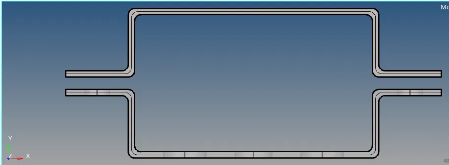
Select offset with keep step jumps method in extraction options while creating midsurface.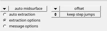
Then delete solid geometries in the model tree to have surface geometries only for meshing.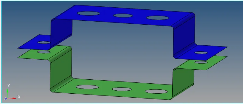
2D Meshing of components:
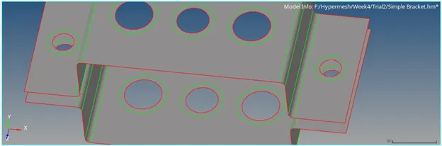
- Add ‘washer split’ of 5mm to the holes on the surfaces.
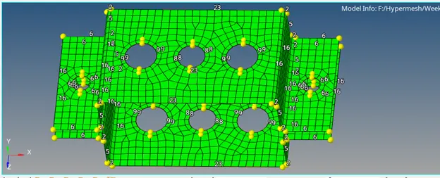
- Create 2D mesh elements of 8mm with size and bias option using automesh option.
Creation of element section for Rod, Beam and Bar.
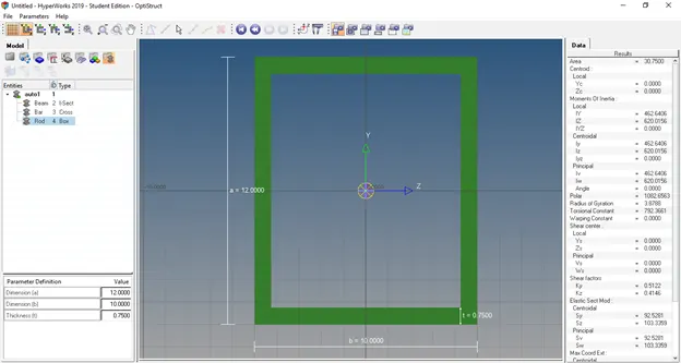
- Create Rod element having box cross section through 1D > HyperBeam > select standard section > choose HyperBeam in standard section library > Thinwalled box in standard section type > click create. Rename it as ‘Rod’ and define the dimension of box a=12mm, b=10mm and thickness=0.75mm.
- For beam section -à Right click in Hyperbeam view tree > create > Standard Section > HyperMesh > select Standard I section. Rename it as ‘Beam’ and define the parameters as given below.
a=8mm, b=10mm, c=8.5mm, t1=0.75mm, t2=0.6mm and t3=0.6mm.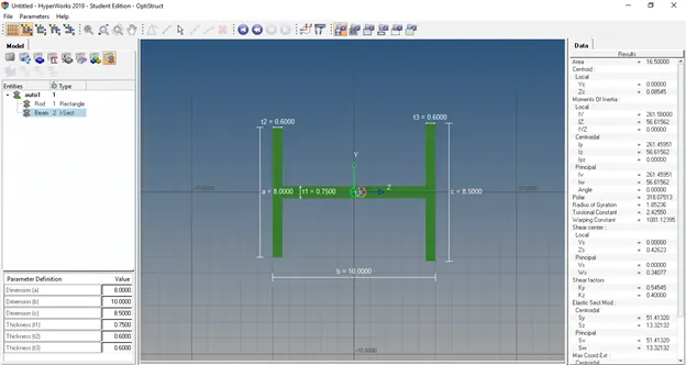
- For Bar section -à Right click in Hyperbeam view tree > create > Standard Section > OptiStruct > select CROSS section. Rename it as ‘Bar’ and define the parameters as given below.
DIM1=5mm, DIM2=1.2mm, DIM3=10mm and DIM4=1.2mm.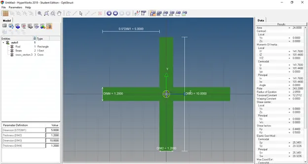
Definition of Material properties for Bracket:
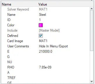
Create a material called ‘Steel’ by right clicking in the model tree > Create > Material and defined its properties as shown below.
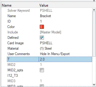
Create Property by right clicking in the model tree > Creator > Property and assigned the material for bracket i.e., Card Image ‘P SHELL’, Material ‘Steel’ and thickness(T) as 2mm.
Definition of Property for Rod, Beam and Bar elements:
- For Rod -à Right clicking in the model tree > Creator > Property > rename it as Rod > select Card Image as ‘PROD’ > select ‘Rod’ section in beamsec.
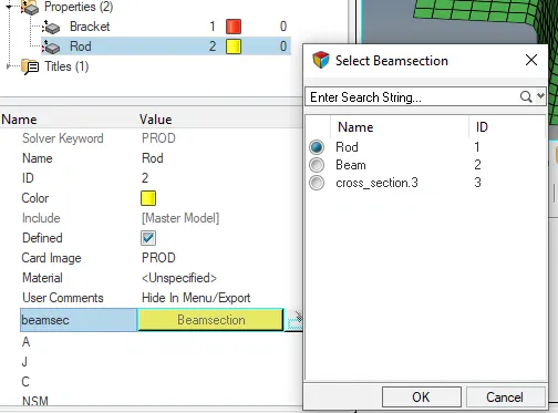
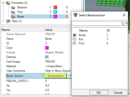
- For Beam -à Right clicking in the model tree > Creator > Property > rename it as Beam > select Card Image as ‘PBeam’ > select ‘Beam’ section in beamsec.
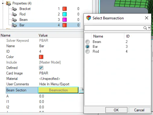
- For Bar -à Right clicking in the model tree > Creator > Property > rename it as Bar > select Card Image as ‘PBAR’ > select ‘Bar’ section in beamsec.
a. Rod Element with RBE2 link and only transition DOF
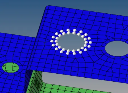
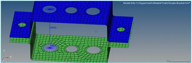
- To select nodes for creating RBE2 link at position ‘a’ in the given figure, Select 1D > rigids > select create > Select Independent as calculate node from the dropdown list > select nodes in GUI using by path option under dependent tab > check transitional DOFs and uncheck rotational DOFs > click create.

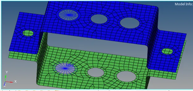
- Select rods in 1D tab > select element type as CROD > select Rod in Property > select first node and second node.
b. Beam Element with RBE3 link and all DOF
- To select nodes for creating RBE3 link at position ‘b’ in the given figure, Select 1D > rbe3 > select create > Select dependent as calculate node from the dropdown list > select nodes in GUI using by path option under independent tab > check all DOFs > click create.
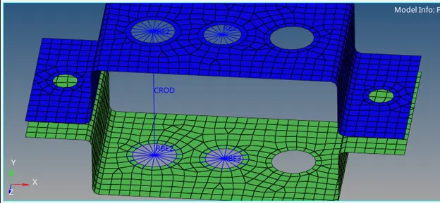
- Select bars in 1D tab > select elem type as CBEAM > select Beam in Property > select first node and second node > select orientation as shown in the image below.
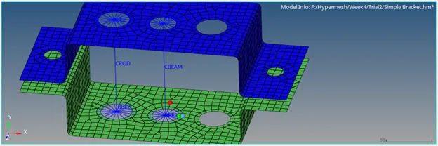
c. Beam Element with RBE3 link and all DOF
- To select nodes for creating RBE3 link at position ‘c’ in the given figure, Select 1D > rbe3 > select create > Select dependent as calculate node from the dropdown list > select nodes in GUI using by path option under independent tab > check x and y DOFs (dof1, dof2, dof4 and dof5) > click create.
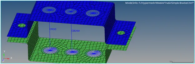
- Select bars in 1D tab > select elem type as CBAR > select Beam in Property > select first node and second node > select orientation as shown in the image below.
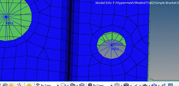
d. & e. Apply Mass of magnitude 10 with RBE2 link at d and e
- To select nodes for creating RBE2 link at position ‘d’ and ‘e’ in the given figure, Select 1D > rigids > select create > Select Independent as calculate node from the dropdown list > select nodes in GUI using by path option under dependent tab > by default all DOFs > click create.
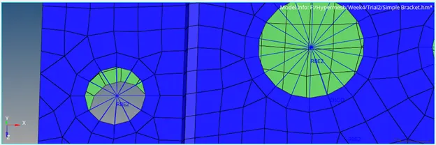
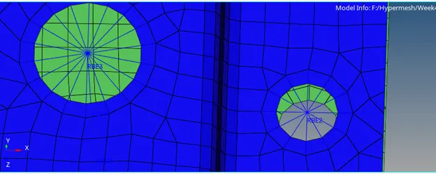
- Select masses in 1D tab > create > define mass = 10 units > select CMASS1in element types > select node to apply mass > click on create.
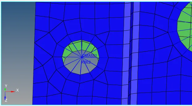
f. Joining two components with Spring elements at f:
- Select springs in 1D tab > select first node and last node.
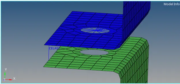
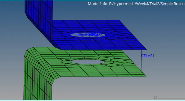
Final model:
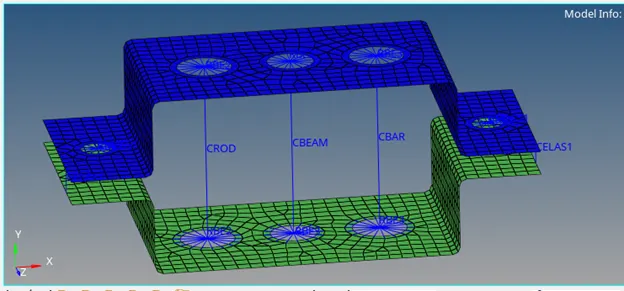
1D Detailed Element Representation
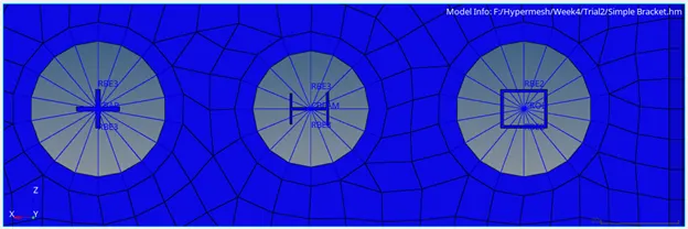
Cross sections of Bar, Beam and Rod elements from Top view