Week 4- Challenge
Objective :
- Need to generate a mesh and deploy 1D elements on generated mesh.
- Defining the cross section to the 1D elements and assigning the property to the cross section.
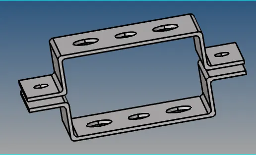
CAD model Image:
Here, I have shown a CAD model below in which we need to generate a mesh and deploy 1D elements.
Procedure:
- First step is we need to generate a middle surface separately for each component. So, that we can work on single item individually with out effecting other part. As shown below I have created to different mid surface with to different color which is assign later.
- Now we need to create a material for each component if there is different material requirement.
- Next step is to create a property where we can assign material thickness as per our requirement.
- After Creating property we need to assign material to respective component.
- By using auto-cleanup Command we can prepare component for 2D mesh. This clean up tools required to prepared material for mesh where we apply washer split and create geometry for required mesh.
- After completing all the above procedure we generate a 2D mesh on component by auto mesh command from 2D menu.
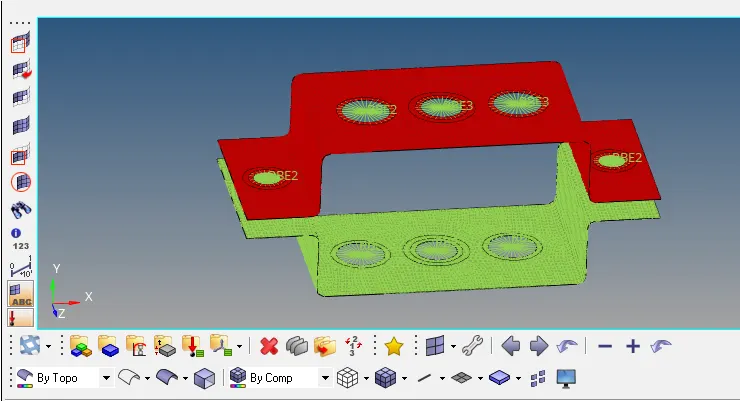
- Here, 2d mesh generating process is completed and now we are going to deploy 1D element on the component from the 1D menu.
* We mostly choose to create 1D element for given model and application rather then 2D or 3D element to reduce a number of nodes and elements so that our meshing and analyzing process can be done faster.
- Before proceeding for to generate a 1d element we need to create a Hyper Beam view model by choosing hyperbeam from 1D menu. Here I have shown another way also for creating hyperbeam for different cross section.
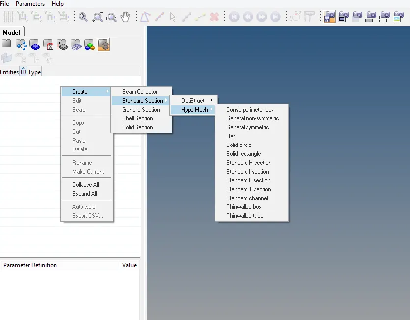
- First of all we are going to create a Rod element model with BOX cross section with given dimensions below.
* Dimension a = 12mm
* Dimension b = 10 mm
* thickness t = 0.75mm
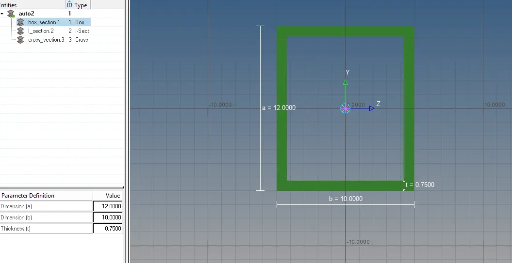
- Second is Beam element model with I Section cross section with given dimension below.
* Dimension a = 8mm
* Dimension b = 10mm
* Dimension c = 8.5mm
* Thickness t1 = 0.75mm
* Thickness t2 = 0.6mm
* Thickness t3 = 0.6mm
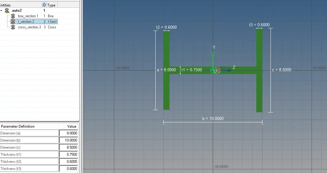
- Third is Bar element model with CROSS cross section which is available is optistruct with given dimension below.
* Dimension DIM1 = 5mm
* Thickness DIM2 = 1.2mm
* Dimension DIM3 = 10mm
* Thickness DIM4 = 1.2mm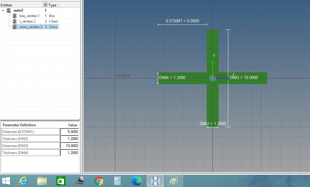
- After Creating all model we going to assign a material and property to the created 1D element model as per requirement.
- Now, completing all the above procedure we are going to create a 1D element on given component as per challenge from 1D menu.
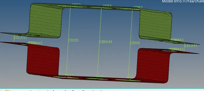
- First we are going to create Rod element at point Awith only translation DOF and RBE2 link by using rod command, rigid command and assign property of Rod which we have already created.
- Then we are going to create Beam element at point Bwith all DOF and RBE3 link by using Beam command, rbe3 command and assign property of Beam which we have already created.
- Next Step is to create a Bar element at point C with only X and Y DOF with RBE3 link by using rbe3 command, bar command from 1D menu and assign property of Bar which we have already created.
- Now we are going to apply a mass with 10 magnitude at point Dand E with RBE3 link.
- Now the last step is to create a spring element at point F by using spring command.
- Final model is look like picture given below.
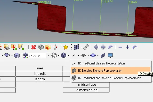
- By clicking button shown in fig below we can show the actual shape to all 1D element.
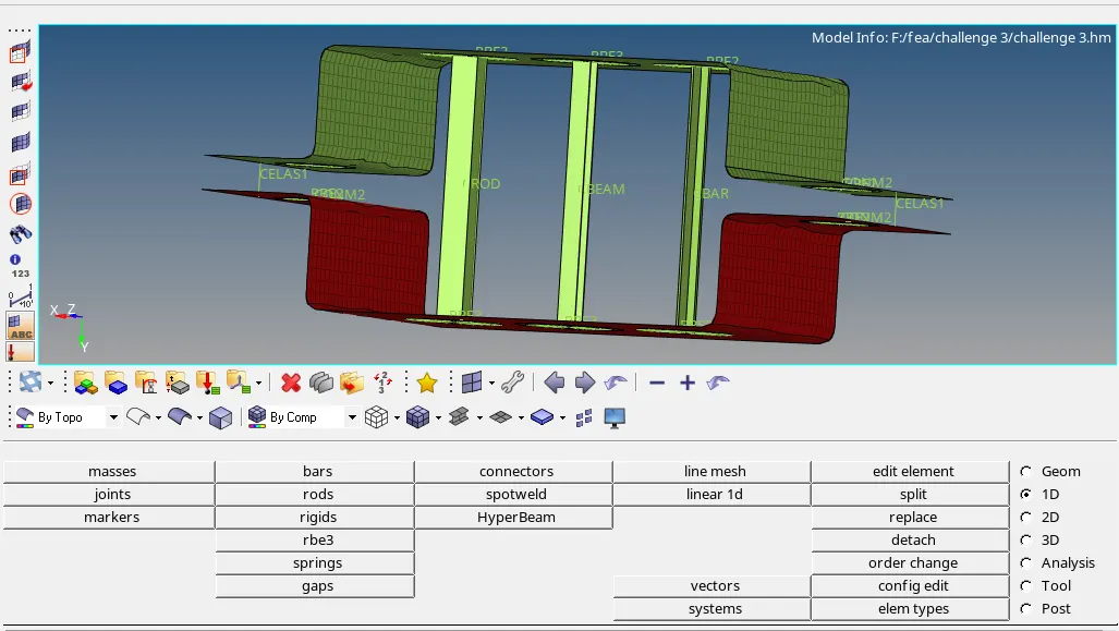
- Our final model out put is shown below.
Final Model Result :