Week - 4
AIM: Implementing control logic of a 'washing machine' using Stateflow in simulink
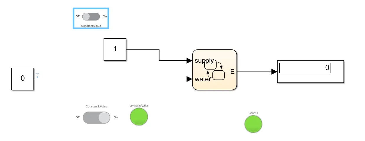
SIMULINK MODEL:
- When water supply is OFF.
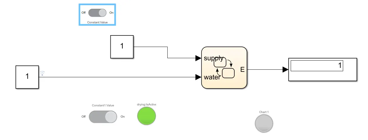
- When water supply is ON.
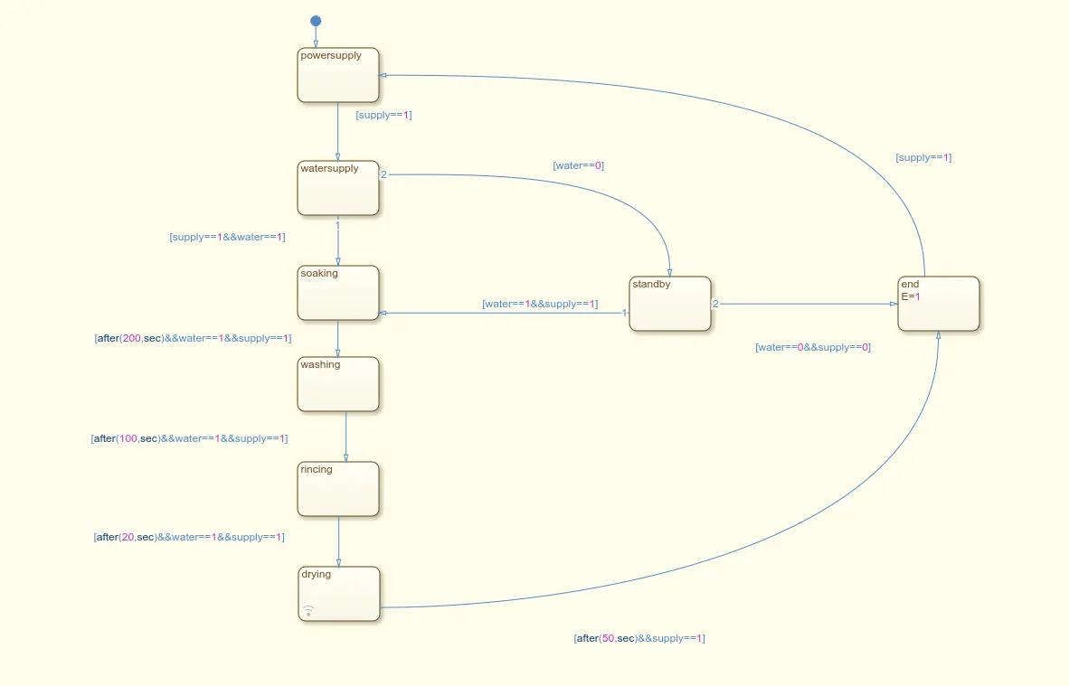
Control logic of a washing machine(stateflow chart):
PROCEDURE:
- Create a stateflow chart for the working process of a washing machine
- give the inputs and the required parameters mentioned in the question
- Run the model by cutting the power supply initially and then run the model again by giving the power supply.
- Provide LED Lamps to indicate that the process has completed.
2.
AIM: To create a simulink chart for the 'gear logic' for the given conditions.
GEAR LOGIC:
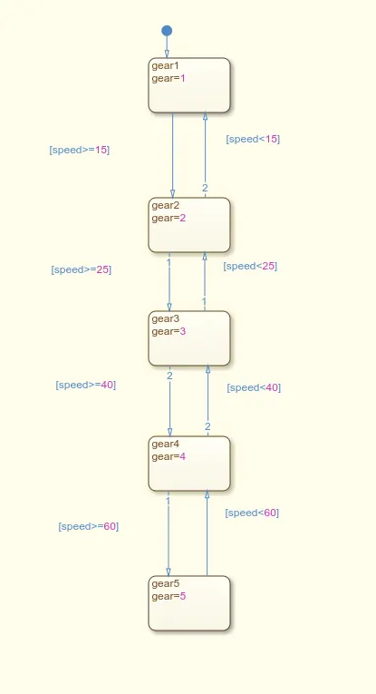
Given conditions;
Speed Range(kmph) Gear
0 to 15 1
16 to 25 2
26 to 40 3
41 to 60 4
Above 61 5
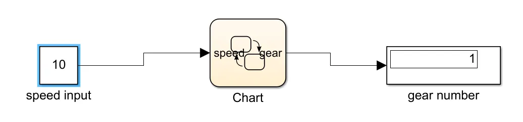
OUTPUT MODEL:
FOR speed=10kmph
FOR speed=50kmph
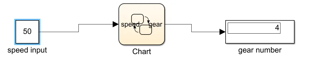
RESULT: Thus using the simulink chart we can arrive at the required gear number for different speeds at which the car is running.