Week 4
AIM: For the given component, check for the geometrical errors and mesh with the given element Quality criteria. After meshing the component, the thickness has to be assigned.
Write a detailed report on your meshing process and also mention which method you used to extract the mid-surface along with the reason.
Given Model Criteria:
|
S.No |
Quality Criteria |
Value |
|
1 |
Target/Average length |
1 |
|
2 |
Minimum Length |
0.5 |
|
3 |
Maximum Length |
3 |
|
4 |
Aspect |
3 |
|
5 |
Warpage |
15 |
|
6 |
Skewness |
45 |
|
7 |
Jacobian |
0.7 |
|
8 |
Minimum Quad Angle |
45 |
|
9 |
Maximum Quad Angle |
135 |
|
10 |
Minimum Tria Angle |
30 |
|
11 |
Maximum Tria Angle |
120 |
|
10 |
Tria Percentage |
15 |
Theory:
Meshing is an integral part of the engineering simulation process where complex geometries are divided into simple elements that can be used as discrete local approximations of the larger domain. The mesh influences the accuracy, convergence and speed of the simulation. Furthermore, since meshing typically consumes a significant portion of the time it takes to get simulation results, the better and more automated the meshing tools, the faster and more accurate the solution.
We can see meshes comprised of triangular or quadrilateral cells (or a combination of the two) in 2D within out model.
Mid surface:
Within the given model only three types of mid surface generation method have been utilized. Ex: Offset, Multi-Middle and Single Middle. The idea is to extract a shell from the solid given to mesh to get quality results.
Offset:
This is a relatively simple process of extraction of mid surface by selecting the face and providing an integer value depending on the direction of the vector.
The important part of this feature is that we can only extract middle surface for components with uniform thickness.
Single-Middle:
In this method we select two faces with uniform or non-uniform thickness and a mid-surface is generated for us.
Multi-Middle:
In this method we use define the 3 faces of the component. The first one is the red surface and then the green which defines the area Ex: Length and breadth.
The third is blue which provides thickness that is width. This generates a mid-surface for the given element.
The Advantage of this method over offset is it considers non-uniform thickness.
Procedure:
- Perform Geometrical check and resolve the issues.
- Generating Mid surface
- Assigning thickness to mid-surface
- Apply given quality criteria
- Create mesh for the entire elements
Methodology in detail:
We import the model into ANSA.
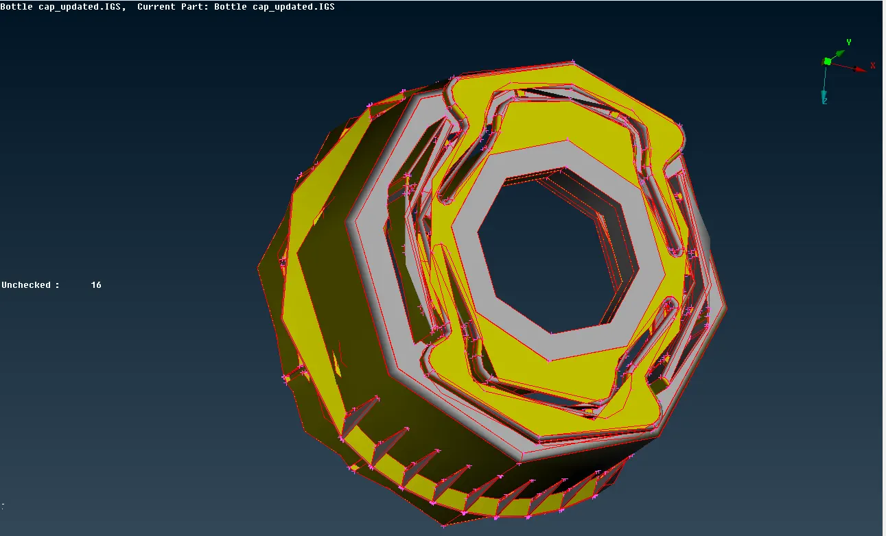
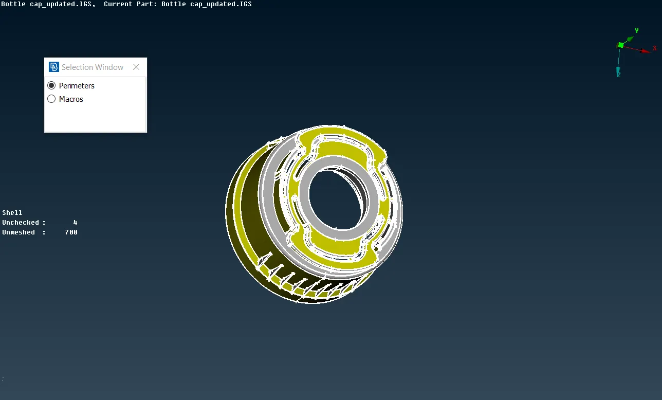
- Secondly for better geometrical resolution we provide perimeter and macros to the predefined requirement.
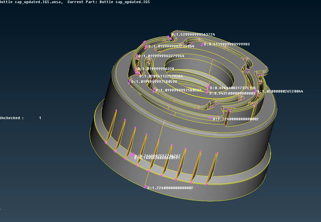
- We measure the elements for thickness so that an appropriate tool can be used for different areas of the component.
- We run a TOPO for the entire component.
- The previous step allows us to run geometrical checks before proceeding any further.
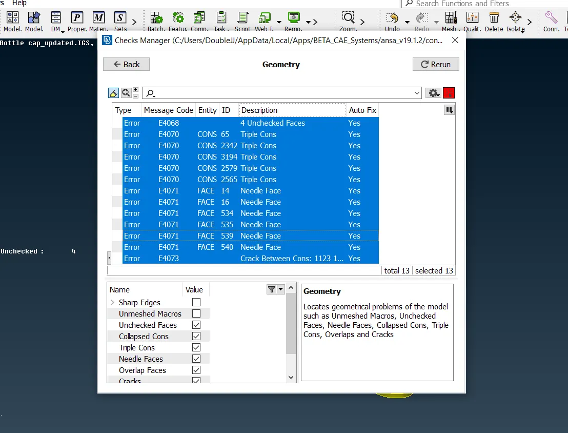
We can correct these errors by selecting them one at a time and resolving them at the source or select all and right click for auto fix which corrects the features to provide a clean geometry.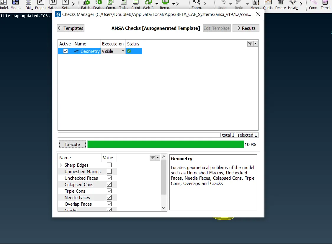
- We then start by extracting middle surfaces for the components for different areas depending on the extraction method utilized.
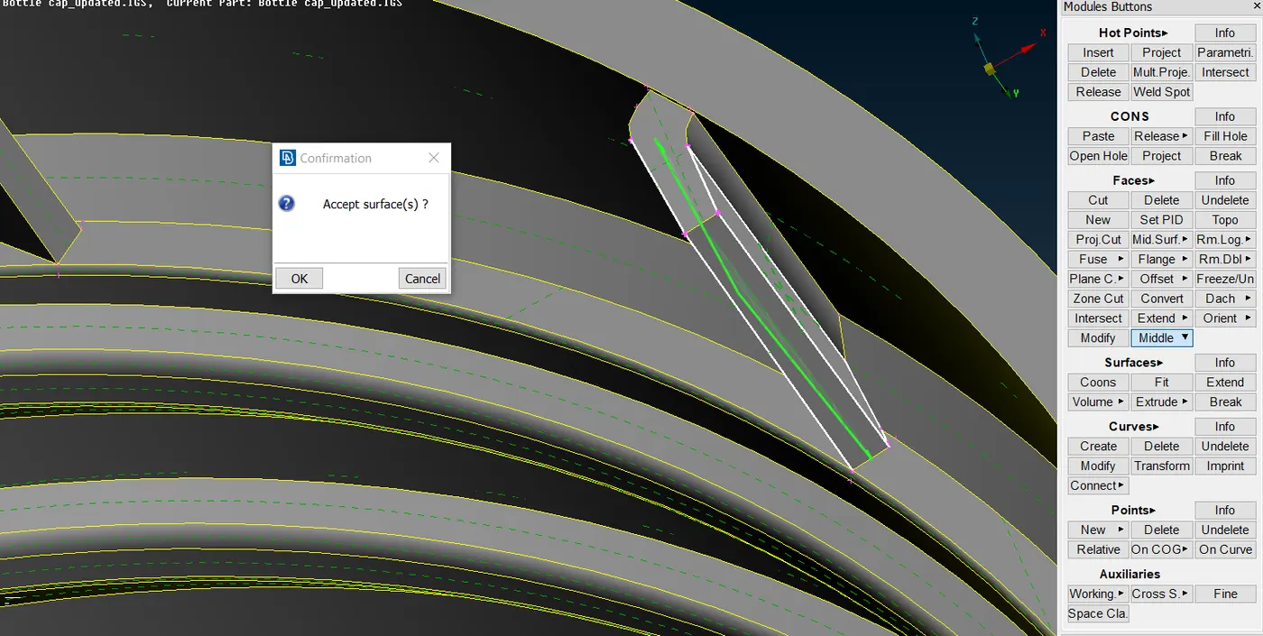
We have taken the option of single middle here at an angle with two of the surface to get precise middle instead of offset.
Here we have used offset as a feature to extract middle due to the uniformity of the surface.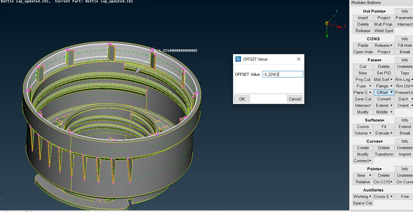
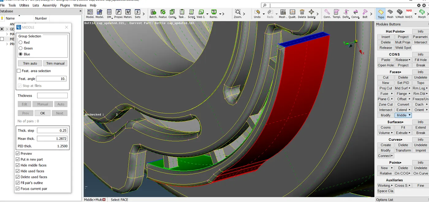
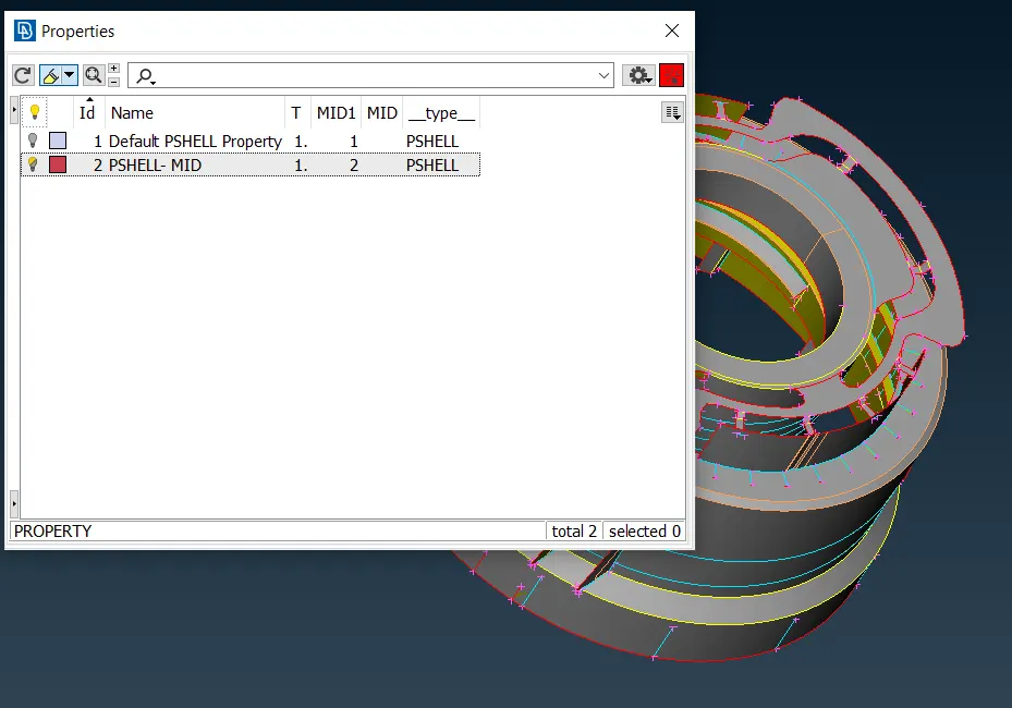
Here we have used multi middle feature to get the varying thickness and get the exact mid. - Once mid surface for the entire component is generated the we define PID for the mid surface as bellow. This can separate for all the components or one single one as well.
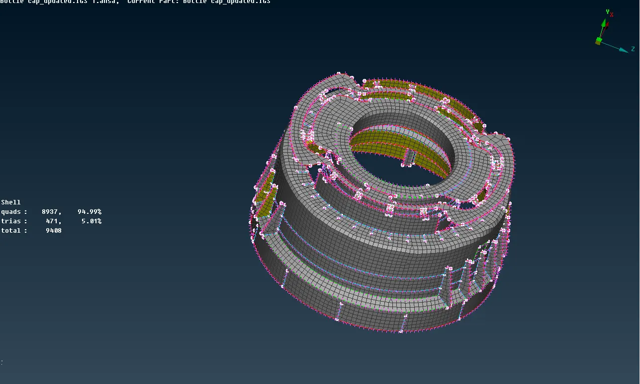
- Now we apply best mesh for the components part by part for better mesh quality.
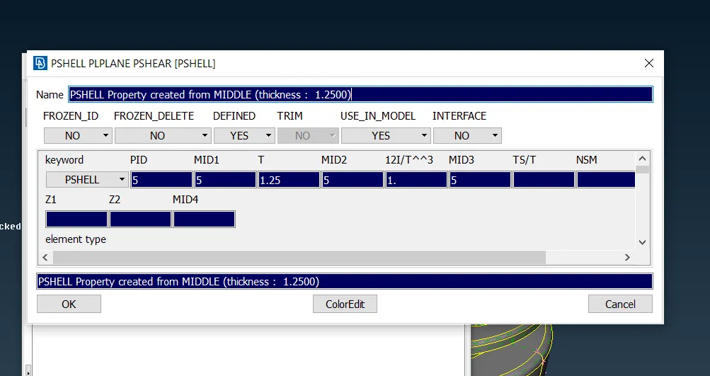
- Assigning thickness provide thickness while assigning the PID of the elements during mid surface extraction.
Learning Outcome:
- Perform Geometrical check and resolve the issues.
- Generating Mid surface
- Assigning thickness to mid-surface
- Apply given quality criteria
- Create mesh for the entire elements
- I learnt pattern generation using rotational option.
Conclusion:
I learnt that meshing is best done in different components when a complex design is present. Dividing the mid surfaces into different PID’s helps.
This helps in managing the mid surface individually and also during meshing.
During meshing individual PID’s helps us focus on one area at a time to get better quality results.