Week - 4
- Implement control logic of a “washing machine” using Stateflow as per given sequence:
- If the power supply is available, the system gets activated
- If the Water supply is not available, stop the process & indicate through LED
- Soaking time should be 200s followed by Washing time of 100s.
- Then rinsing happens for next 20s & dryer runs for 50s
After all the processes have completed turn on the finished LED
Simulink Model : 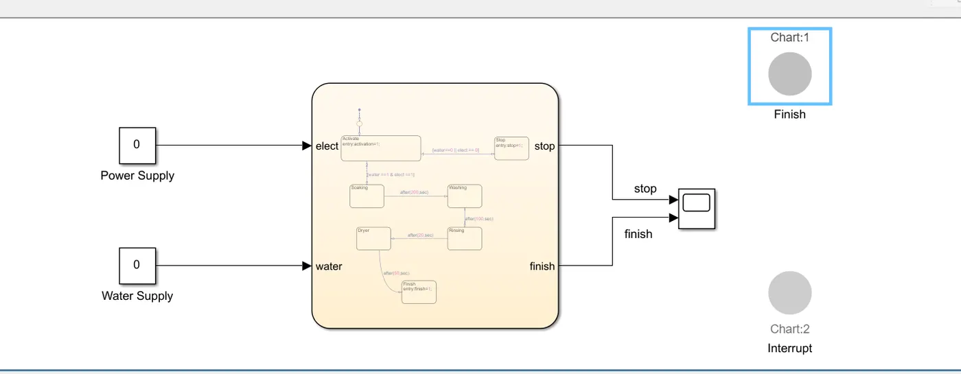
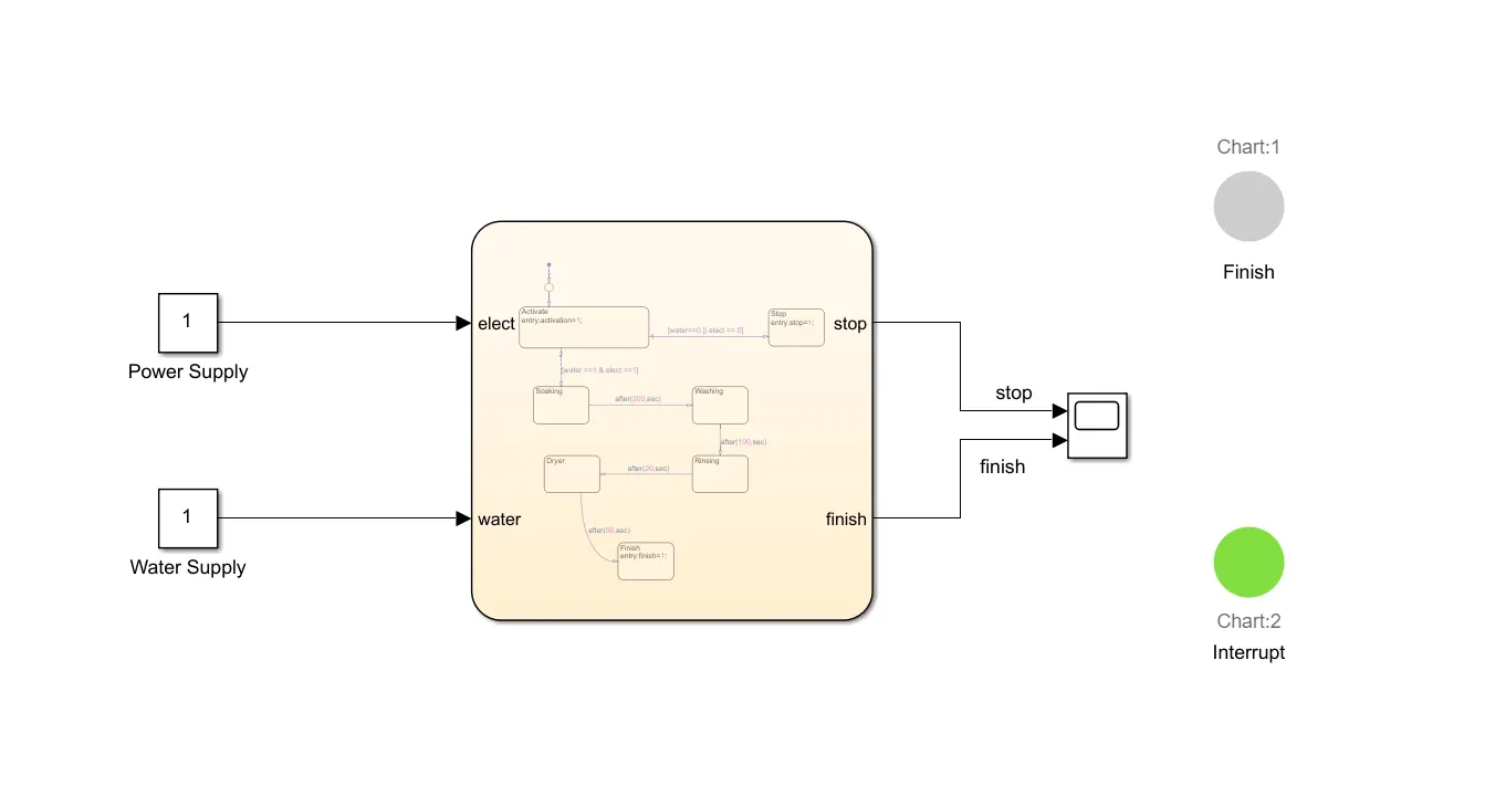
When Power Supply and Water supply is Present :
When Both Are not Present :
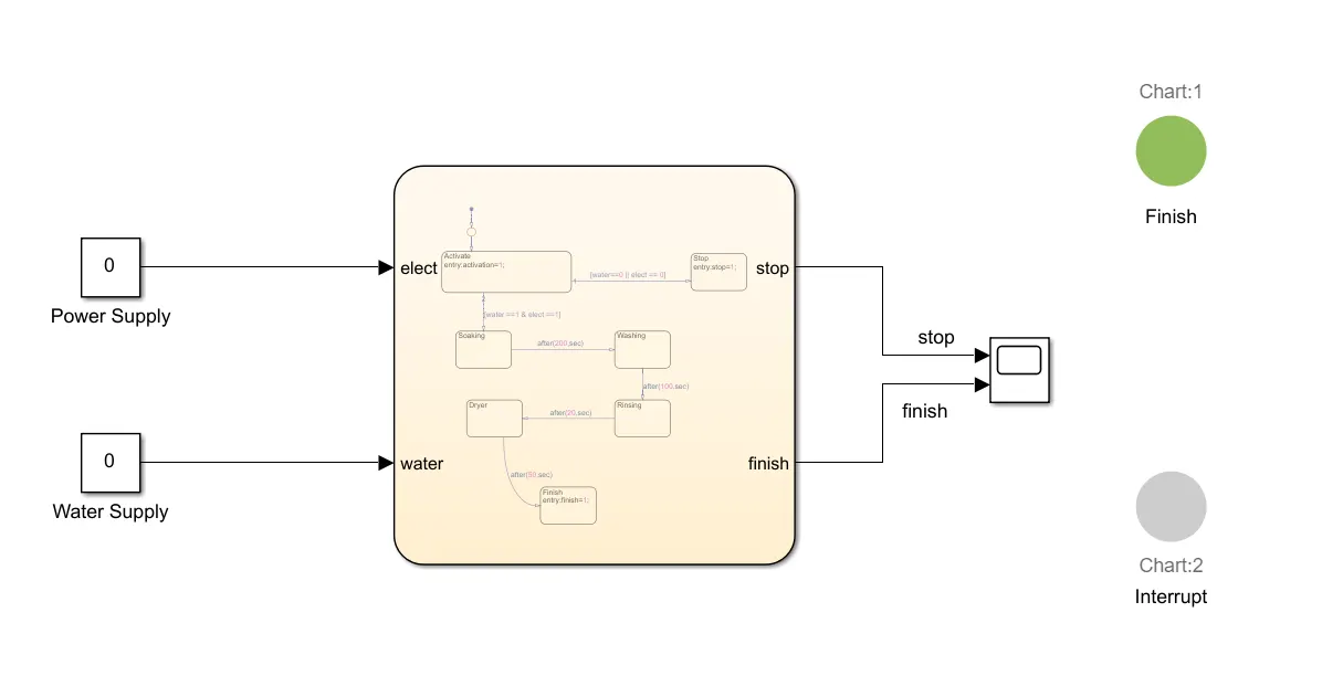
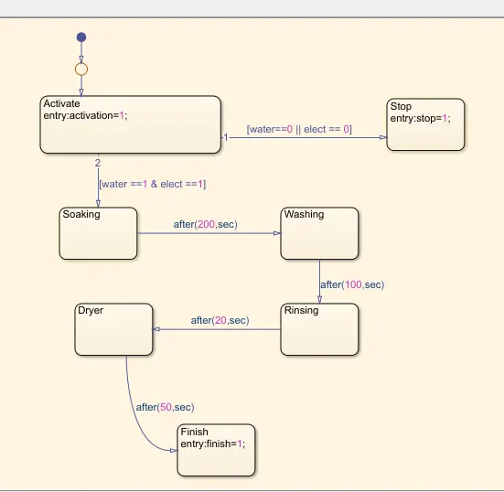
The washing machine control logic is implemented using Stateflow in MATLAB/Simulink, where different states represent various phases of the washing cycle. The system starts by checking if both power (elect) and water (water) supply are available. If either is missing, the process stops, and a "Stop" LED is activated (stop = 1). Once both power and water are available, the machine transitions to the Soaking phase, where clothes are soaked for 200 seconds before moving to the Washing phase for 100 seconds. After washing, the system enters the Rinsing phase for 20 seconds, followed by the Drying phase for 50 seconds. Upon completion of the drying process, the machine transitions to the Finish state, where a "Finish LED" is turned on (finish = 1) to indicate that the washing cycle has completed.
In Stateflow, inputs (elect, water) control the activation of the washing machine, while outputs (stop, finish) are used for status indicators. The Symbol Panel in Stateflow is configured to define these input and output variables. The transitions between states are governed by time-based events (after(x, sec)) and logical conditions. The washing machine process is visualized in Simulink by connecting the Stateflow chart with constant blocks for input signals and LED indicators for output signals. If at any point the power or water supply is lost, the system immediately moves to the Stop state, ensuring safety and proper operation. This control logic can be further enhanced by adding user input controls, an emergency stop feature, and real-time status displays in Simulink.
===============================================================================================================================
2. Make a Simulink chart for the “Gear shift” logic as per below conditions:
Speed Range(kmph) Gear
0 to 15 1
16 to 25 2
26 to 40 3
41 to 60 4
Above 61 5
Give speed input while the simulation is running & display the gear number.
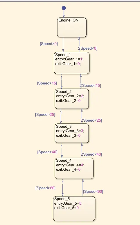
The given Stateflow model represents a gear shifting logic for an automated transmission system based on the vehicle's speed. The system starts in the Engine_ON state, and as the speed increases, the system transitions through different gears. The first gear (Gear_1) is engaged when the speed is greater than 0 and remains active until the speed exceeds 15. When the speed surpasses 15, the system shifts to the second gear (Gear_2), and the first gear is deactivated. This process continues as speed increases: Gear 3 is activated when speed exceeds 25, Gear 4 engages when speed surpasses 40, and finally, Gear 5 is selected when speed is greater than 60.
Conversely, if the speed decreases, the system downshifts accordingly. For example, if the speed drops below 60, the system shifts from Gear 5 back to Gear 4. Similarly, if speed falls below 40, it moves to Gear 3, and so on, until returning to Gear 1 when speed is below 15 or stopping entirely when speed is 0 or negative.
The transitions between states are controlled by conditional checks on speed, and each state has entry and exit actions where a specific gear is engaged (entry: Gear_X = X;) and the previous gear is disengaged (exit: Gear_X = 0;). This logic mimics real-world automatic gear shifting in vehicles, ensuring smooth operation by dynamically adjusting gears based on speed. This model can be further enhanced by adding parameters like engine load, acceleration, and braking inputs for a more realistic driving simulation.
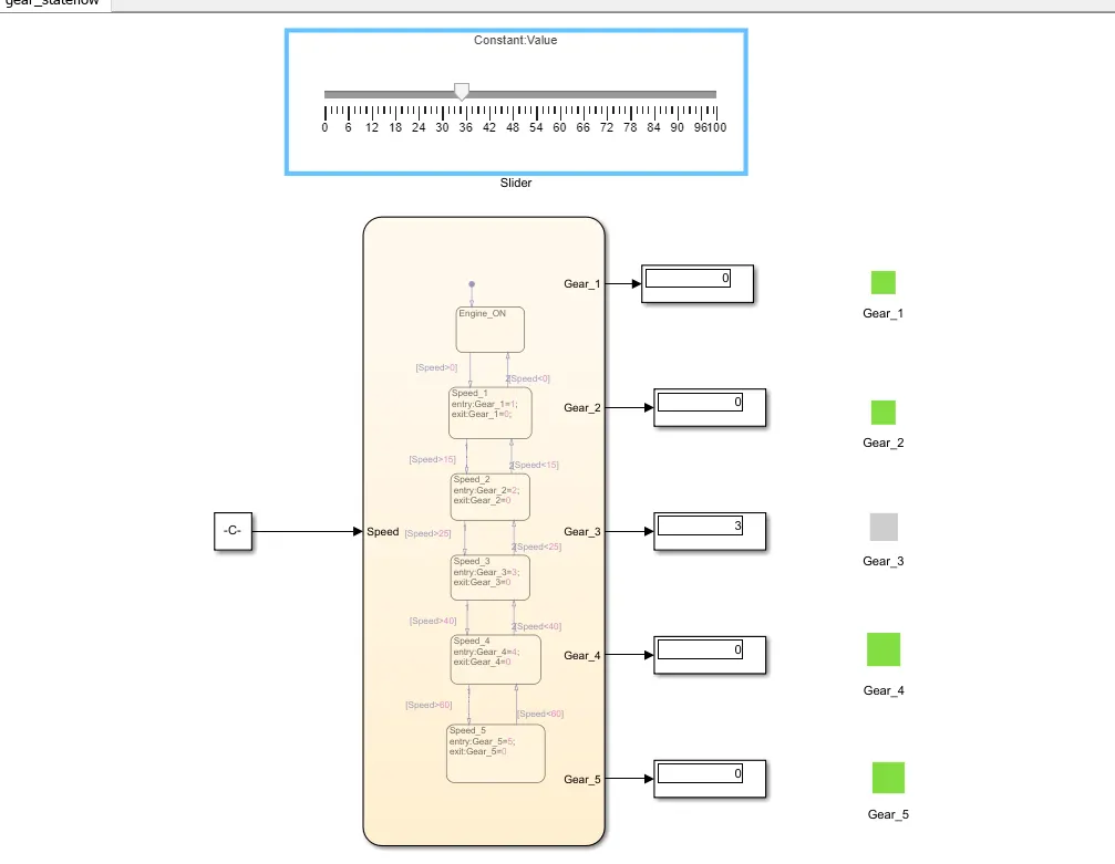
Stateflow-based gear shifting logic in Simulink. The system takes speed as an input, controlled by a slider at the top, which acts as a constant value input. The speed value is fed into the Stateflow chart, which determines the gear selection based on predefined speed thresholds. The chart follows a sequential gear-shifting mechanism: Gear 1 is engaged when speed is greater than 0, Gear 2 activates above 15, Gear 3 above 25, Gear 4 above 40, and Gear 5 above 60. Similarly, the system downshifts when the speed drops below the respective thresholds.
The right side of the image contains indicators and numeric displays representing the gear states. Each gear has an associated green or gray indicator, where green signifies that the respective gear is engaged, and gray indicates it is inactive. In this particular instance, Gear 3 is active, as indicated by the numeric display showing "3" and the corresponding indicator in gray, while the other gears remain inactive with green indicators.
This Simulink-Stateflow model effectively demonstrates an automatic transmission system, which dynamically selects gears based on speed input. Such a model can be further improved by incorporating acceleration, braking, or load conditions for a more realistic simulation of a vehicle's transmission behavior.