Week - 4
Implement control logic of a “washing machine”
Blocks used
Chart
Constant
Display
Lamp
Rocker switch
Lamp and Switch creation
rocker switch
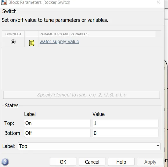
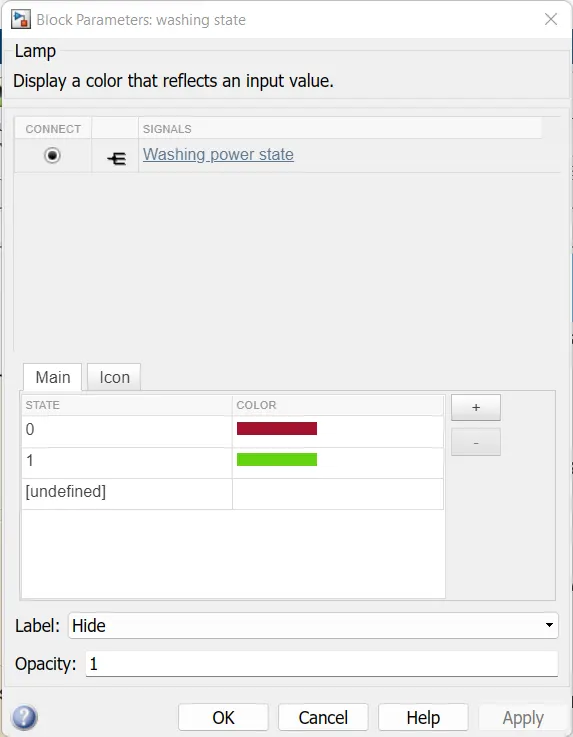
Washing machine logic
chart
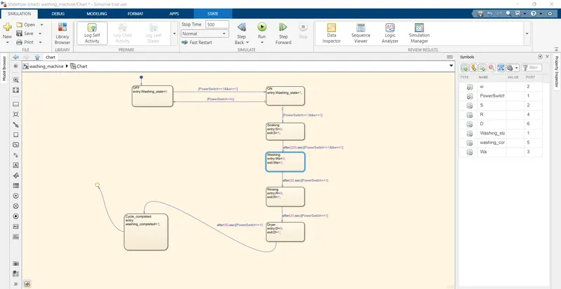
Explanation
- In the above control logic first state is created with 2 conditions for power supply.
1. With power supply available (PowerSwitch==1)
2. With water supply available
- (W==1) If the power supply at entry is 1 and water supply is ON then machine will get activated and start the next process of operation.
- Next 4 Operation states have been created in flow order Soaking, Washing, Rinsing, Drying with their time of operation as 200sec for a soak, 100sec for wash,20 sec for rinse & 50sec for dry
- Entry and exit condition of the state are kept as 0 & i.e at entry of operation states it is o and ie at entry of operation states it is 0 and as operation completes it is 1 for every states.
- After all process has done washing machine completed LED will glow and we can shut the machine off.
Simulink model showing that the washing process completed
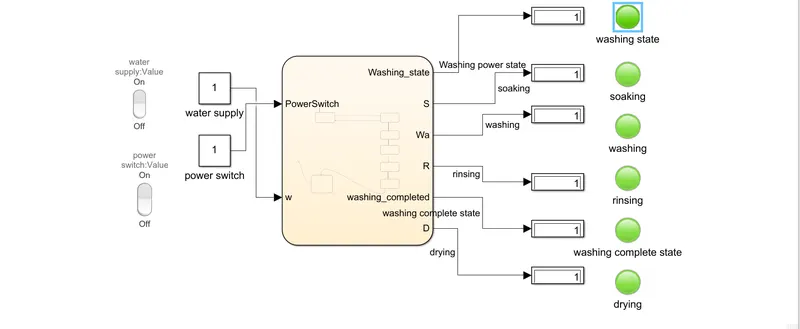
here all lights are green so all process has been completed and all display out as 1
Simulink model showing that the washing process completed and Rinsing is going on
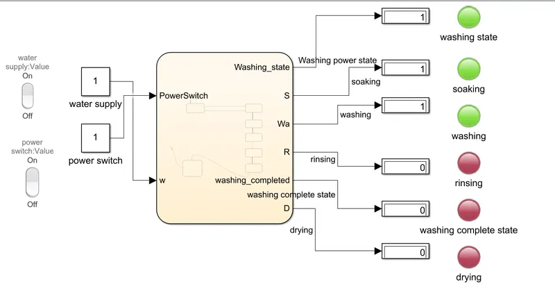
here green light means operation is completed and red light means operation is not completed
2 Make a Simulink chart for the “Gear shift”
Blocks used
- Chart
- Lamp
- Constant
- Display
- Slider
- Rocker switch
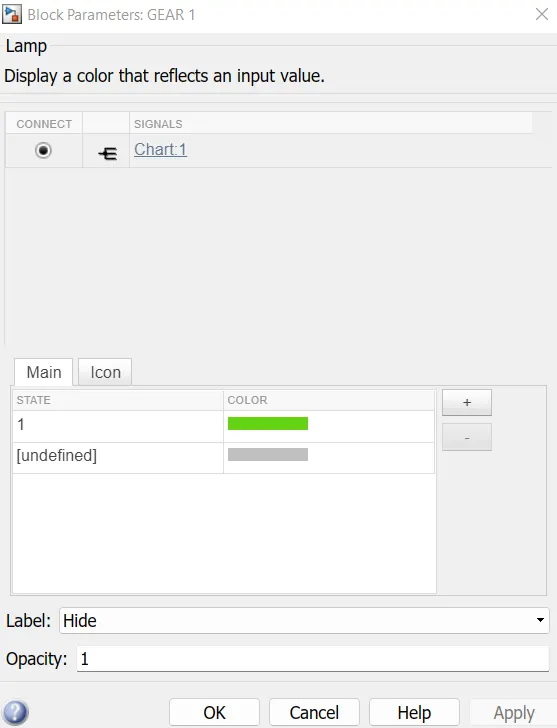
Lamp creation
As Gear
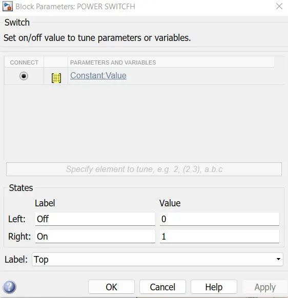
Rocker switch creation
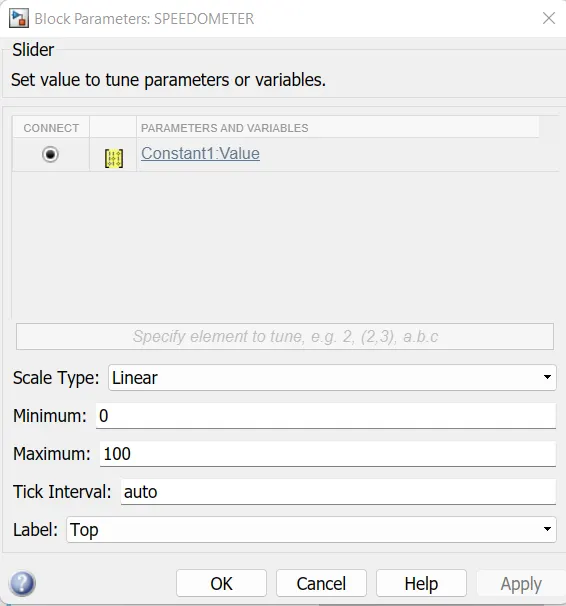
Slider creation
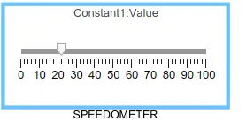
Logic and chart for gear shift in simulink
- In slider the speed ranges from 0 to 100 and the slider is used to send the input
- The 1st gear has speed values from 0 to 15 so the entry condition for the 1st gear is 0<-speed and speed<=15 and the exit condition is when the speed greater than 15
- Similarly for 2nd gear the entry condition is 16<=speed and speed<=25 the exit condition is when speed<16 and speed>25
- In the same way for each gear the entry and the exit condition are specified and the out is mapped to the lamp and the display block
Chart and Symbols pane
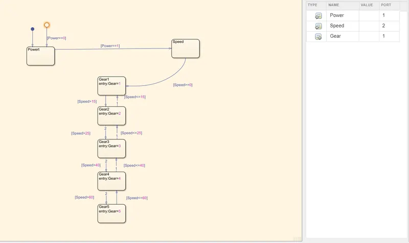
- In this control logic 1st Engine is started from input switch E=0/1 through Rocker switch
- Which is power switch to make engine ON
- Five Gear State is created with state condition of gear 1,2,3,4,5 respectively and their transition is connected with speed range condition as shown
Speed>15 shift to G = 2
Speed>25 shift to G = 3
Speed >40 shift to G = 4
Speed 60 shift to G = 5 when the speed is increasing from 0-60 kmph
- similarly in reverse direction
Speed 60 shift to G = 4
Speed 40 shift to G = 3
Speed 25 shift to G = 2
Speed<15 shift to G = 1 when the speed is decreasing from 60-0 Kmph
Simulink at different speed
at 100,45,35,20,10
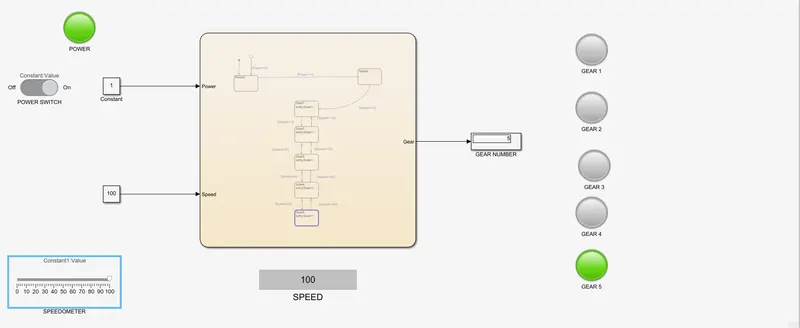
In 5 th gear
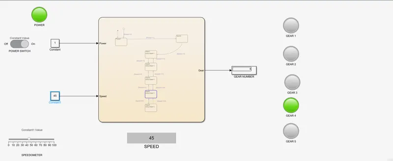
In 4 th gear
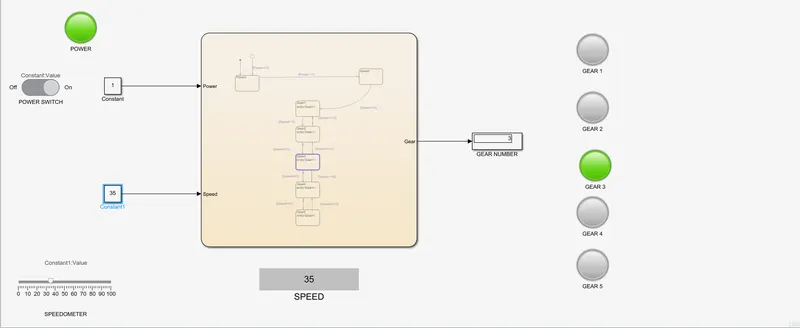
In 3 rd gear
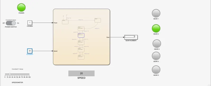
In 2 gear
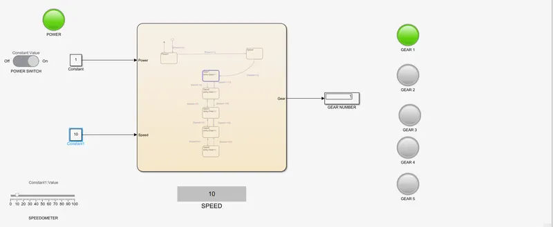
In 1 st gear
The link of the wasing machine
https://drive.google.com/file/d/1Q721JyJMV8K0o_VQSpo0-0B-zW5aLnEw/view?usp=sharing
The link of the gear
https://drive.google.com/file/d/1IKIUU_lJEzAgwb2myf-LiCAleRrnSwaN/view?usp=sharing