Week - 4
1) Washing Machine control logic using Stateflow
In the Stateflow part of the washing machine control logic, there are 6 states as shown in the figure
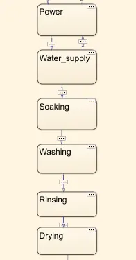
there are certain conditions in which the code transfers control between the states the first condition for entering into the power state is the power button should be on in the input part of the model, if not the logic isn't moved further on, and all the states remain inactive. When the control enters the power state the action is provided in the state as power = 1 which controls the action of the lamp in the model outside the chart. And same entry and exit actions are provided in each state that controls the action of their respective lamps.
After the power there comes the water supply state the condition for entering into this state is the water valve must be open in the input part if not the control remains in the power state.
And then if the power and water supply are on the control is transferred to the soaking state where it remains for 200 secs and then to the washing state for 100 sec after it moves into the rinsing and drying state for 20 secs and 50 secs respectively.
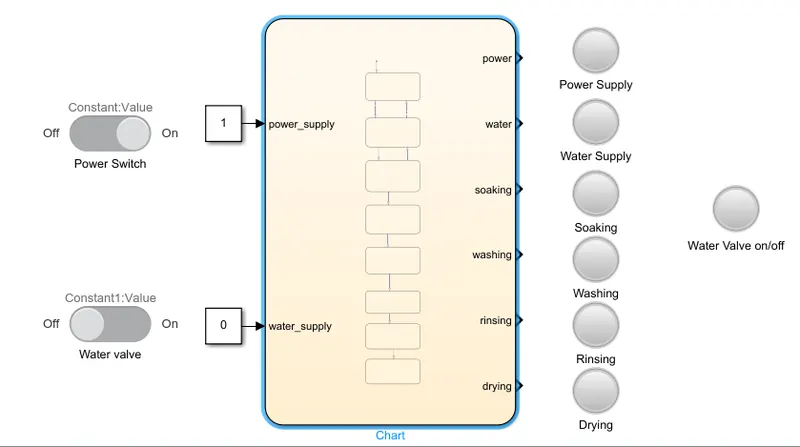
In the model part as shown in the figure below on/off buttons are provided which control the values of the constant block which are the inputs to the chart for power supply and water connection and lamps are provided to indicate the control is transferred between each state and to indicate whether the water valve is open or closed an extra lamp is provided
2)Gear shift logic
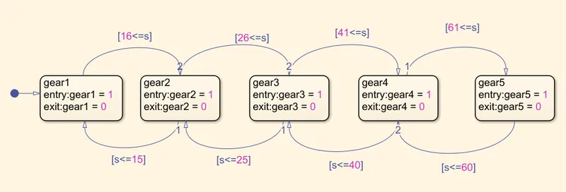
In the control logic of the gear shifting mechanism, there are five states belonging to each gear and the conditions for moving on to the other and returning back to the state are the speed limits provided in the challenge for each gear here variable 's' is used for speed input.
In each state, the entry and exit actions are provided i.e. if control enters the state the output value of that gear would be 1 and if it exits the output value would be 0 this action further controls the lamp of the respective gears in model
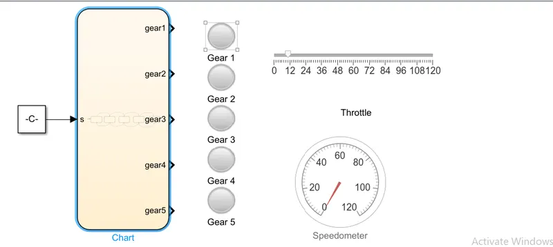
The input of the speed variable is controlled by the constant block which gets its input from the slider bar in the model which is labeled as throttle and a full gauge is also provided in the model which indicates the value of the speed that is provided as an input.