Week - 4
Problem - 1
Objective :- Implement control logic of a “washing machine” using Stateflow as per given sequence:
- If the power supply is available, the system gets activated
- If the Water supply is not available, stop the process & indicate through LED
- Soaking time should be 200s followed by Washing time of 100s.
- Then rinsing happens for next 20s & dryer runs for 50s
After all the processes have completed turn on the finished LED
Theory :- In washing machine there are different operating state which operate one after another in sequence.The operating states in washing machine are soaking, washing, rinsing and drying.This states get in operation mode depend on conditions and state transition is according to duty which based on time delay.
Implementation of control logic for a “washing machine” using Stateflow :- Before implementing the control logic of any machine we have to understand working condition and various states of that machine. As mentioned in our problem statement following are the working condition of washing machine-
- If the power supply is available, the system gets activated
- If the Water supply is not available, stop the process & indicate through LED
- Soaking time should be 200s followed by Washing time of 100s.
- Then rinsing happens for next 20s & dryer runs for 50s
Implementation of control logic for a “washing machine” using Stateflow is shown in following images-
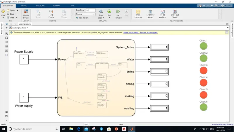
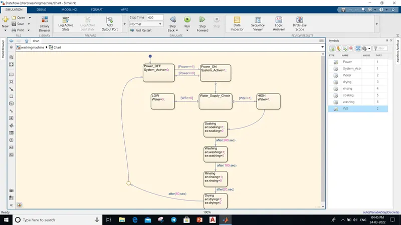
Explanation of Simulink Model :- First I select Chart block and open it after that stateflow window get open.For creating different states I select 'state' option in stateflow window.As shown in above image there are two blocks "Power_OFF" and "Power_On" for checking power supply. If we give Power==1 as a input then as ouput we get System_Active=1 and lamp colour get green, whereas if we give Power==0 as a input then as ouput we get System_Active=0 and lamp colour get red. From Power_ON block system get transfer to "Water_Supply_Check" block where it check for input signal "WS".Based on WS input value we get output either 'Water=0' or 'Water=1'.From 'HIGH' block system get transmitted to others states Soaking,washing, rinsing and drying respectively in sequence based on given time delay. After completion of all process with the help of 'Junction' option in stateflow we again go to starting state.At last by using 'Symbol Pane' option I mentioned the type of all unrecognised name.
Result :- After running the model we get above result .If power supply is available we get 1 value at 'System_Active' port and lamp associated with this signal get green otherwise we get 0 value and lamp indicate red colour.Simillarly, for water supply if water is available we get 1 value at 'Water' port and lamp associated with this signal get green otherwise we get 0 value and lamp indicate red colour.For states , if we get value as 1 at output port and lamp green means that process under operation in washing machine.
NOTE :- 'washingmachine.slx' file is attached.
************************************************************************************************************************************************************************************************************
Problem - 2
Objective :- Make a Simulink chart for the “Gear shift” logic as per below conditions:
Speed Range(kmph) Gear
0 to 15 1
16 to 25 2
26 to 40 3
41 to 60 4
Above 61 5
Give speed input while the simulation is running & display the gear number.
Theory :- In gear shift logic gear get changed based on the sensed value of speed. There are different gears such as 1, 2,3,4,5 that get in operation for particular speed range.
Simulink chart for the “Gear shift” logic :- Before drawing simulink chart we have to understand the state transition and the input condition of given system.The following image shows simulink chart for Gear shift logic based on the conditions that mentioned in above objective.
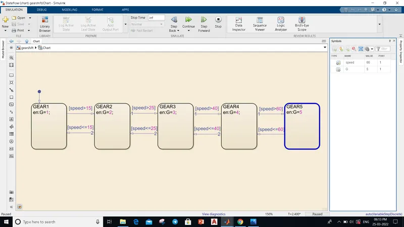
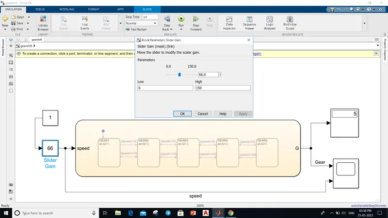
Explanation of Simulink Model :- First I select Chart block and open it after that stateflow window get open.For creating different gear states I select 'state' option in stateflow window.As shown in above image there are five state block for gear 1 to 5.Here speed is input parameter based on value of speed gear state get shifted. And 'G' is output which get shown on disply.For changing the speed I used 'slider gain' block from simulink library.
Result :-
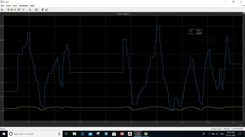
After running the simulink model we get above result. For different value of speed gear get shifted to particular gear number.
NOTE :- 'gearshift.slx' file is attached.
************************************************************************************************************************************************************************************************************