Week - 4
ANSWER-1
AIM:Implement control logic of a “washing machine” using Stateflow as per given sequence:
- If the power supply is available, the system gets activated
- If the Water supply is not available, stop the process & indicate through LED
- Soaking time should be 200s followed by Washing time of 100s.
- Then rinsing happens for next 20s & dryer runs for 50s
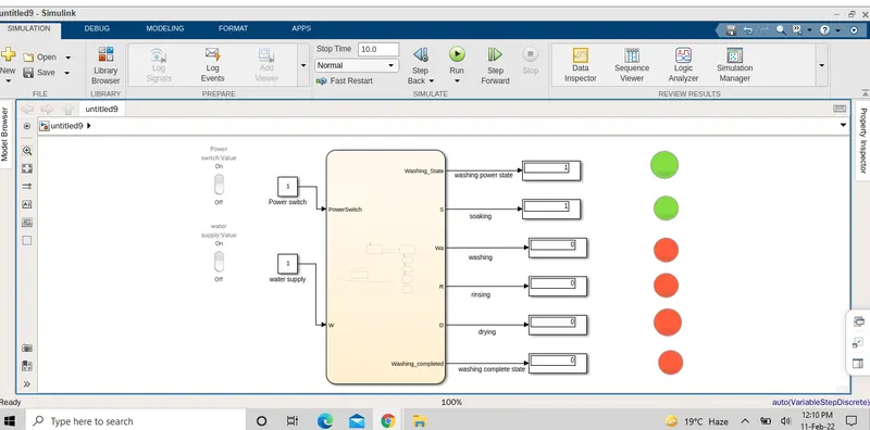
EXPLANATION: A Rocket switch is used with a constant to supply the power and water supply.A lamp is used to indicate the power status and water status .The power status is checked at thr entry for every state and the water supply is checked for the soaking and the rinsing process.The timing for each state is as per the given inputs.The status of the running process can be seen by green and red colour.The green colour means process is running and red colour means the process is not in service.
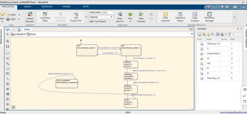
The stateflow is shown above, in this stateflow chart the washing machine logic : first state is created with 2 conditions for power supply and water supply availability with the condition PowerSwitch==1 and W==1 respectively.If the power supply at entry is 1(on) and water supply is1( on ), then washing machine will get activated and next for operation have been created in flow order Soaking,Rinsing,Drying,with their time of operation of 200 sec for a soak,100 sec for wash,20sec for rinse and 50 sec for dry.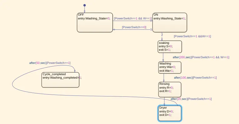
Entry and exit condition as 0 and 1 respectively which means if process completes it shows exit state that is 1.After each process completes the red LED turns into green LED.
If any of 2 conditions for power supply and water supply availability not satisfied,then machine will stopped .
RESULT:Here 2 conditions for power supply and water supply availability with the condition PowerSwitch==1 and W==1 respectively are satisfied,so machine gets started, the next soaking has started and after 200 sec the washing will start. As the process completes the the red LED turns into green LED.
_________________________________________________________________________________________________________________________________________________________________________________________________________________________________________________________________________________________________________
ANSWER 2.
AIM:Make a Simulink chart for the “Gear shift” logic as per below conditions:
Speed Range(kmph) Gear
0 to 15 1
16 to 25 2
26 to 40 3
41 to 60 4
Above 61 5
GIVEN: Speed inputs while the simulation is running & display the gear number
EXPLANATION:The speed ranges from 0 to 100 kmph and for gear change according to the slider :
| speed range(kmph) | gear | entry condition | exit condition |
| 0 to 15 | 1st | 0<=speed & speed<=15 | speed>15 |
| 16 to 25 | 2nd | 16<=speed & speed<=25 | speed>25 |
| 26 to 40 | 3rd | 26<=speed & speed<=40 | speed>40 |
| 41 to 60 | 4th | 41<=speed & speed<=60 | speed>60 |
| Above 61 | 5th | 61<=speed |
The speed ranges from 0 to 100 and the slider is used to send the input.The 1st gear has speed values from 0 to 15 so the entry condition for the 1st gear is 0<=speed & speed<=15 and the exit condition is speed>15.Similarly for 2nd gear,the entry condition is 16<=speed & speed<=25 and exit condition is when speed>25.In the same way for each gear ,the entry and exit condition specified.
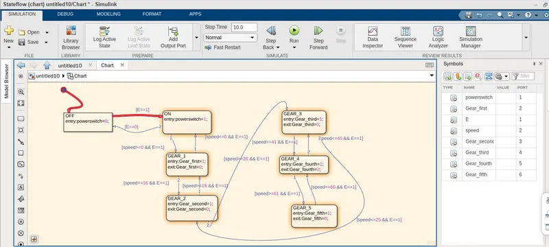
RESULT: when engine is on (value=1), suppose speed is 72kmph,so it shows the fifth gear display shows 1 output with LED glowing and other display is 0 with no LED glows.
simlarly at speed 26kmph, it shows the third gear display shows 1 output with LED glowing and other display is 0 with no LED glows.
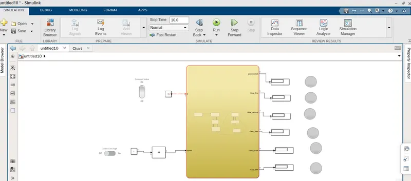
Thus all condition simulated through stateflow chart sucessfully
__________________________________________________________________________________________________________________________________________________________________________________________________________________________________________________________________________________________________________