Week - 4
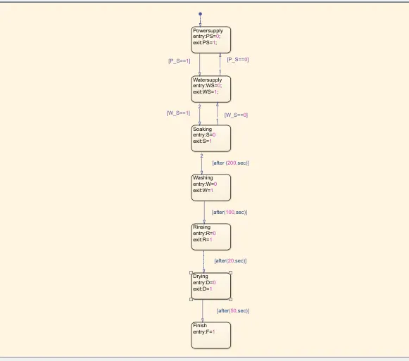
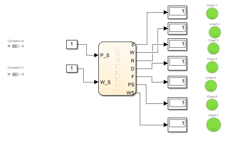
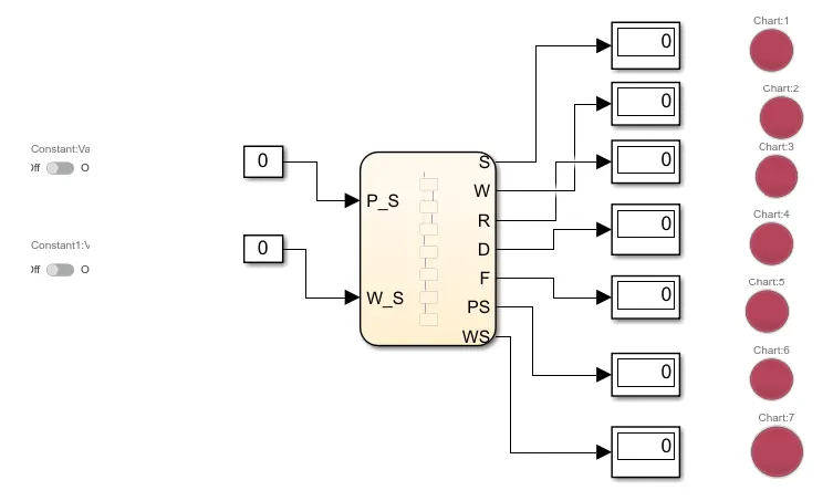
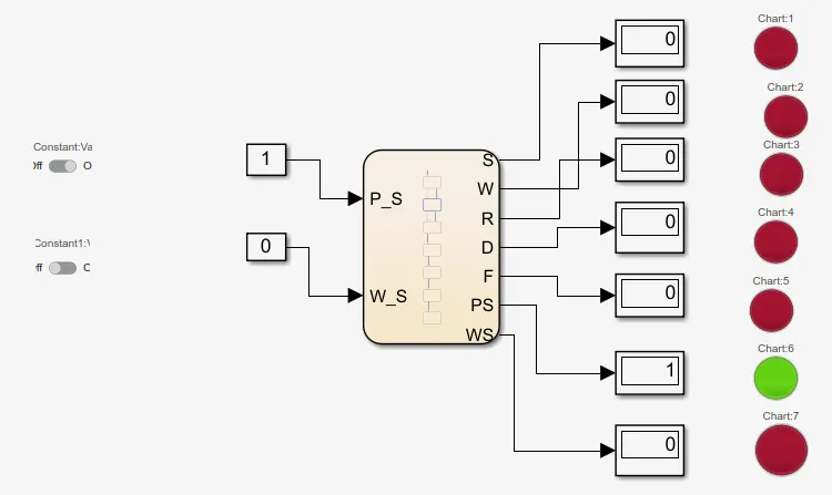
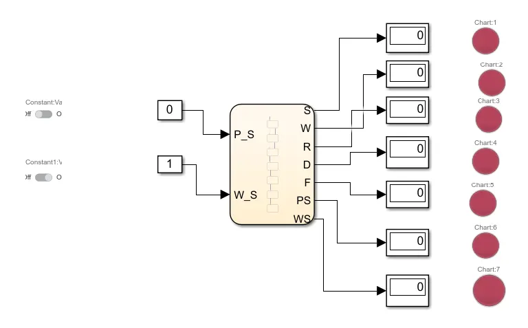
- Implement control logic of a “washing machine” using Stateflow as per given sequence:
- If the power supply is available, the system gets activated
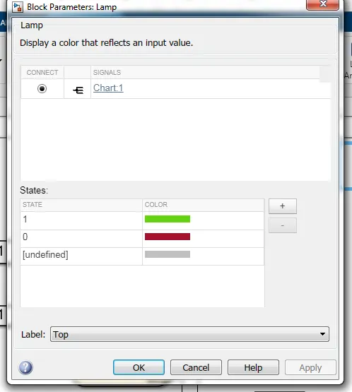
- If the Water supply is not available, stop the process & indicate through LED
- Soaking time should be 200s followed by Washing time of 100s.
- Then rinsing happens for next 20s & dryer runs for 50s
After all the processes have completed turn on the finished LED
CONTROL LOGIC:
Control logic is the part of a controller that defines how a reactive system responds to events or conditional changes. Applications for control logic include:
- Supervising how to switch between different modes of operation
- Scheduling a sequence of tasks or steps for a system
- Defining fault detection, isolation, and recovery logic
Common tasks for modeling control logic include:
- Modeling hierarchical state machines for large-scale systems
- Adding flow charts to define complex control logic
- Defining orthogonal states to represent systems with parallelism
STATE FLOW:
Stateflow® provides a graphical language that includes state transition diagrams, flow charts, state transition tables, and truth tables. You can use Stateflow to describe how MATLAB® algorithms and Simulink® models react to input signals, events, and time-based conditions.
Stateflow enables you to design and develop supervisory control, task scheduling, fault management, communication protocols, user interfaces, and hybrid systems.
With Stateflow, you model combinatorial and sequential decision logic that can be simulated as a block within a Simulink model or executed as an object in MATLAB. Graphical animation enables you to analyze and debug your logic while it is executing. Edit-time and run-time checks ensure design consistency and completeness before implementation.
Washing Machine :
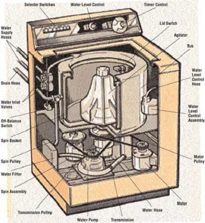
A washing machine is a home appliance used to wash laundry. The term is mostly applied to machines that use water as opposed to dry cleaning or ultrasonic cleaners. The user adds laundry detergent, which is sold in liquid or powder form, to the wash water.
Description :
2. Make a Simulink chart for the “Gear shift” logic as per below conditions:
Speed Range(kmph) Gear
0 to 15 1
16 to 25 2
26 to 40 3
41 to 60 4
Above 61 5
Give speed input while the simulation is running & display the gear number.
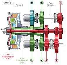
Vehicle transmissions require devices to match the ratio, and thus the power available, to the prevailing driving conditions. “Power matching” is one of the four
main functions of a vehicle transmission. In manual gearboxes, changing gear is
controlled and carried out by the driver. Depending on the amount of automation,
in all other gearboxes electronics and actuator systems take over this function partially or completely. Certain transmission functions, such as Neutral, Reverse, and
Park are however still controlled by the driver using a shifting device.
The gearshifting mechanism thus plays an important role in the interface between driver and vehicle. Its handling has a major influence on perceived comfort.
The components used in a gearshifting mechanism depend largely on whether
shifting gear involves interrupting the power flow. Other factors are the type of
vehicle (passenger car or truck), the type of drive (front-wheel or rear-wheel
drive) and the operating conditions. In the following discussion, a distinction is made between
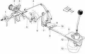
• internal shifting elements:
shifting elements inside the transmission, such as selector bars, swing forks,
synchronizers, multi-plate clutches
• external shifting elements:
shifting elements outside the transmission, such as gearshift levers, gearshift
gate, linkage, four-bar linkages and cable controls.
The concept “shift-by-wire” pertains to the substitution of mechanical gearbox operation with electronic operation .
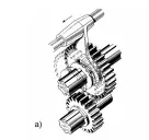
assembly group in gearboxes that shift with power interruption (MT, AMT) and
are also used in dual clutch transmissions (DCT). This important internal shifting
element is dealt with thoroughly
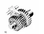
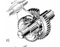
multi-plate clutches as essential components when shifting without power interruption. The parking lock is an assembly group whose function is to prevent vehicles that have no mechanical coupling between the engine and the output from
rolling away (AT, DCT and CVT). This is the topic of shows
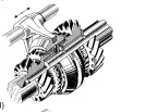
power flow. A distinction is made between positive locking clutches (e.g. dog
clutch) and friction clutches (e.g. multi-plate clutch).
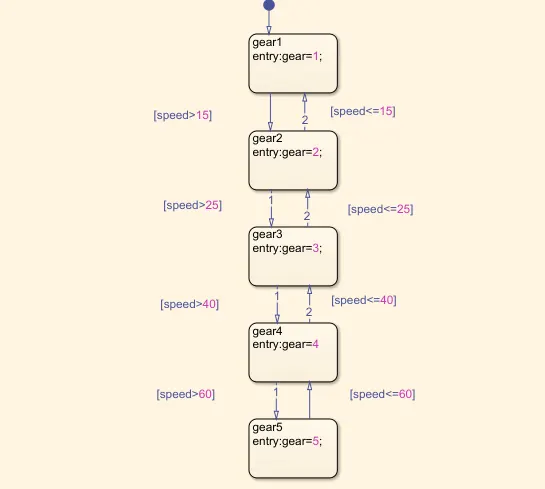
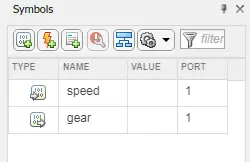
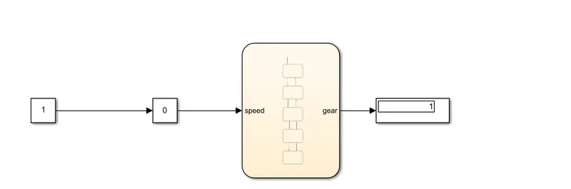
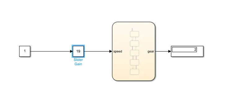
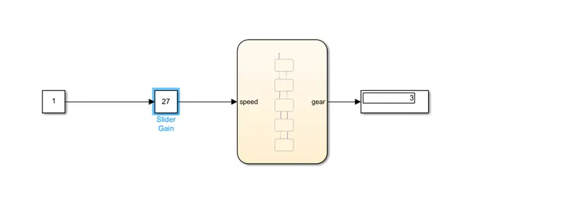
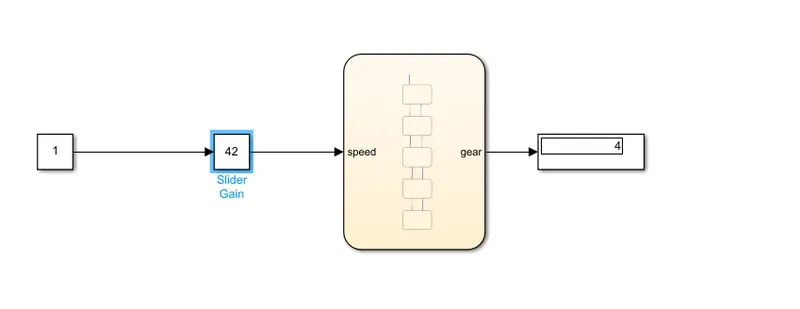
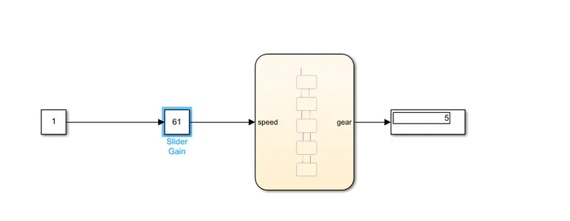
the “Gear shift” logic as per below conditions:
Speed Range(kmph) Gear
0 to 15 1
16 to 25 2
26 to 40 3
41 to 60 4
Above 61 5 for all conditions we satisfyed
CONCKLUSION:
1) The control logic flowchart by using this we implemented the control logic of a washing machine
2) By using control logic flow chart we satisfiyed different conditions in gear shift