Week 4 - 2D Meshing for Sheet Metal
Meshing of Cross Car Beam
AIM: To mesh the entire Cross Car Beam Assembly
PROCEEDURE:
Part Analysis
The entire assembly model has in total 34 parts. These parts have to be selected separately in particular groups and meshed.
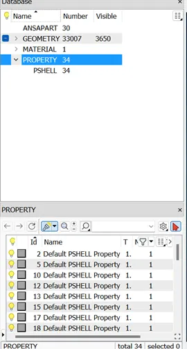
Here, feasible parts are selected in groups and their mid surface is generated. The geometric cleanup is done for each and every mid surface.
Quality mesh parameter:
The mesh parameter is defined as per the requirements
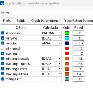
The above parameter should be followed for the elemental meshes. If this criterion is not followed then the mesh elements fall under off elements.
Parts Bifurcation:
The parts are selected out and grouped separately while geometric clean up is to be done and the parts to be meshed. This avoids the complexity of the meshing and the geometric clean up.
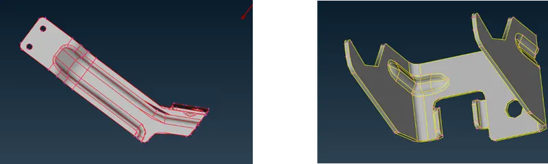
This type of meshing and geometric clean up is way much easier than meshing them together.
Geometric Cleanup:
As Initially the cons of the model are undefined i.e., we can see the red cons instead of the yellow. This type of cons is corrected with the help of options such as paste, topo, cut.
Also, the surfaces are damaged has to be addressed and deleted and new surfaces is generated whenever required.
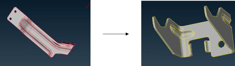
In the above examples there are two different geometries out which one of it has well structure yellow cons but another one doesn’t. Such red conned surfaces needed to be corrected.
Meshing Technique:
As this an assembly consisting of a greater number of parts an automatic mesh generation technique will be less time consuming. Also, the parts of the assembly have smaller sizes and less complicated structure so the automatic mesh generated here also gives a considerably good mesh flow.
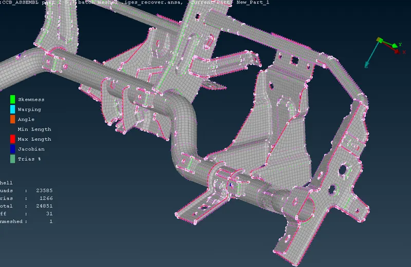
The most used meshing tech here is batch mesh. However, in the complicated regions we have to go for spot mesh. Also, after batch meshing, there are regions of mesh quality failure so there it has to be reconstructed swapped etc.
For Batch meshing initially a mid-surface is generated either by middle option or by offset option. This mid surface is assigned as a new PID & new part. The quality parameter input is given to the batch mesh and then run option is used for batch meshing.
Assigning Thickness:
Once the mid surface is meshed it is assigned with the thickness in the PID tab. The value of the thickness is decided by the dimension of the parent element. In this project value of thickness varies somewhere around 1.6mm to 2mm.