Week - 4 - 2D meshing for Plastic components
AIM
|
TO CHECK FOR GEOMETRICAL ERRORS OF PLASTIC BOTTLE CAP MODEL MID SURFACE EXTRACTION USING BEST POSSIBLE COMMAND TO DECREASE TIME OF PREPROCESSING. MESH GENERATION OF UNIFORM FLOW THROUGH OUT THE MID SURFACE OF CAD GEOMETRY AS GIVEN MESH PARAMETER AND QUALITY CRITERIA. |
OBJECTIVE- For the given Plastic Bottle Cap model, check for the geometrical errors and take the mid surface by suitable mid surfacing techniques.
PID and Thickness assignment has to be done for all the mid surfaces. Mesh the same with given element Quality criteria.
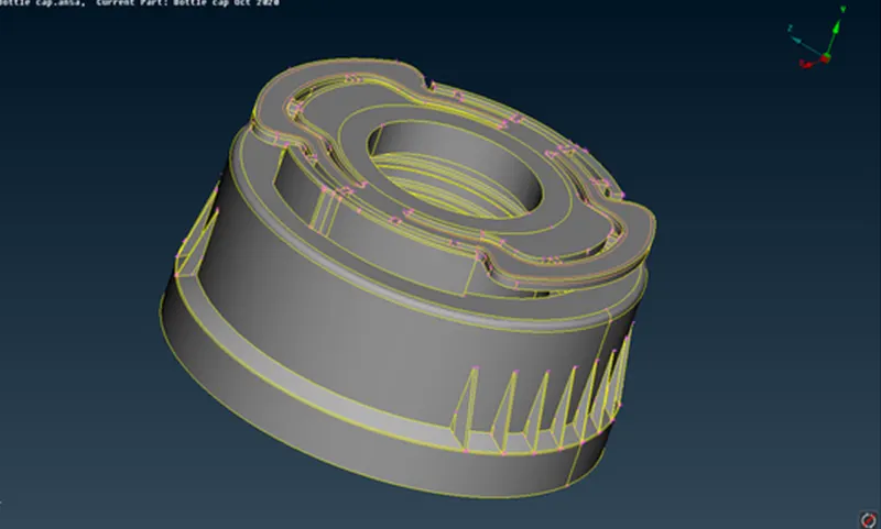
PROCEDURE -
1. Cad geometry setup - Topo, Proper Orientation, Geometry Cleanup.
1 (a). Doing the Topology and correcting the orientation of the given part using Topo and Orient Command.
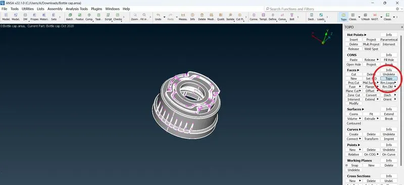
Applying Topo Command in the Topography Section
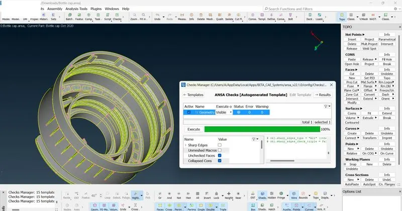
1 (b). Proceeding for geometrical checks of CAD model through checks manager .
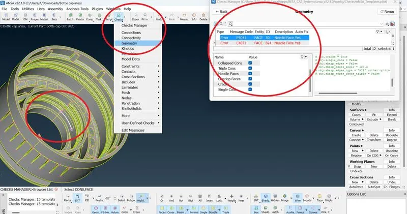
ANSA Checks manager shows total 2 needle face error .
We can highlight any of the problematic areas by left-clicking on it, or isolate it on the screen by right-clicking on it and selecting “Show only”.
Depending on the type of the problem ANSA also offers the option to automatically fix it.
ANSA can automatically fix these geometrical errors but for analytical purpose we are going to fix these geometrical errors manually.
Needle face error is just a error arises due to coincidence of cons of opposite faces. We can simply delete that needle face from choosing appropriate face id.
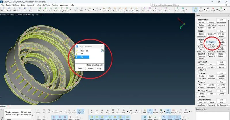
After deleting the needle face id, we can perform topology to stich sharing edges and features lines. Or we can automatically fix errors by auto fix option.
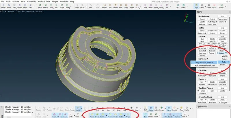
After Geometry Cleanup, Topo & proper orientation we can move towards the next step i.e. Mid Surface extraction.
2. Mid Surface Extraction .
2 (a). Since given component is of plastic, hence thickness of different sections of part may vary.
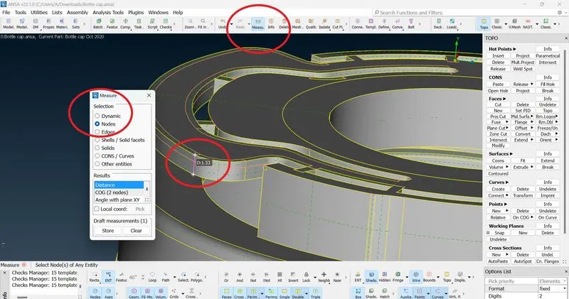
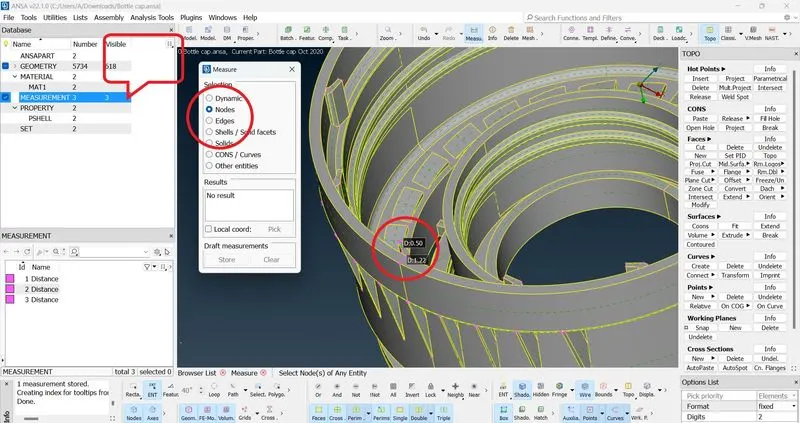
Image showing diffferent thickness of different sections/features ( Highlighting, stored measurement)
2(b). Now, how to approach a component for mid extraction ? ( From where to start?)
For the given component we can start with the main body first then we move towards the component featrures like fins, ribs threads etc.
2(c). For extracting the mid surface we are using the manual extraction method using offset command.
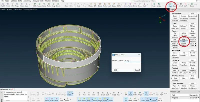
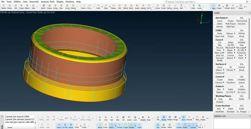
Image showinh extracting the main body first, then moving towards the features.
In a similar fashion we can extract the mid surface of the complete component.
Extraction method for the critical features like threads and teeths.
In the given component, we encoutered some critical features like threads and tapered teeth, we extrated their mid using following method.
1. Take the curve middle of the threads in the width ( its not possible to take the mid of the entire trapezium section using shell mesh)
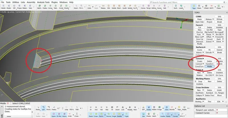
2. Now move the extracted middle curve to the mid surface using not button.
3. Project those curve on the extracted surface.
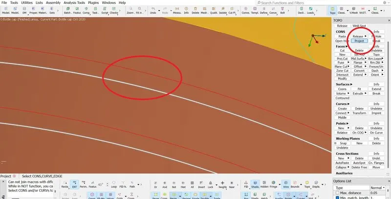
4. Now create a new surface between the curves using new command
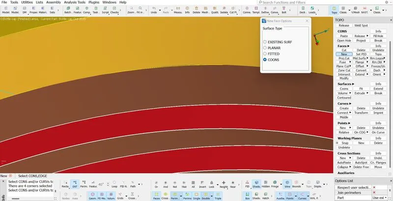
Hence our threads are extracted. In a similar fashion our teeths can also be extracted.
Similarly we can extract mid of different feaatures.

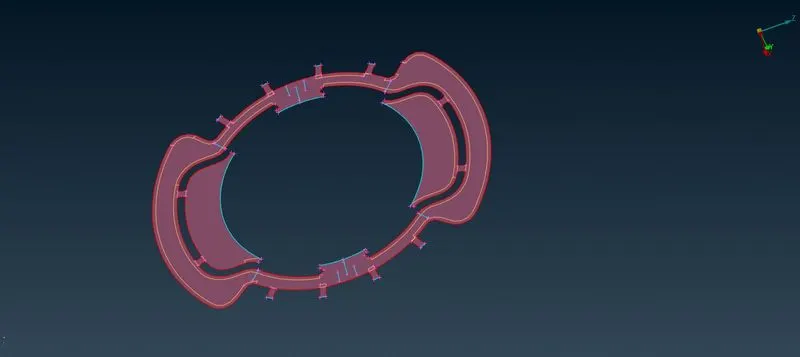
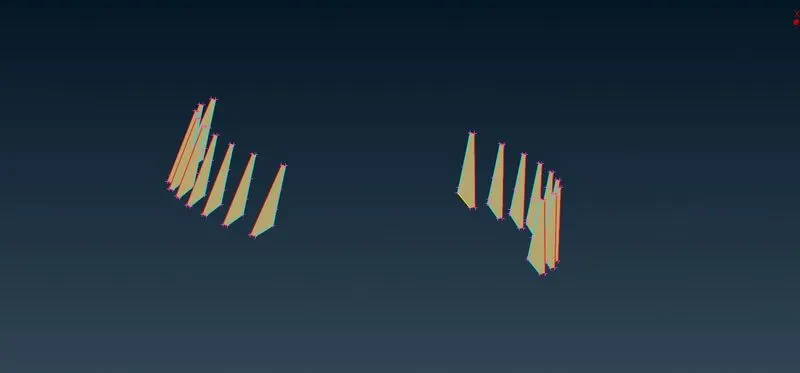
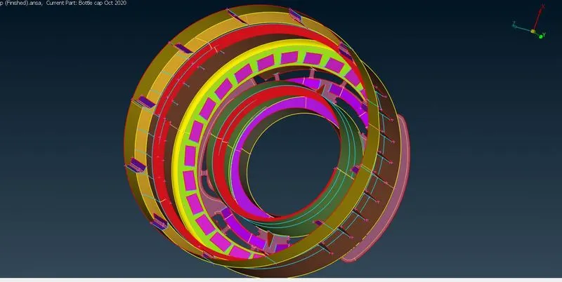
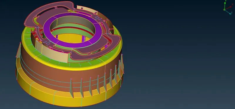
Complete Mid Surface extracted.
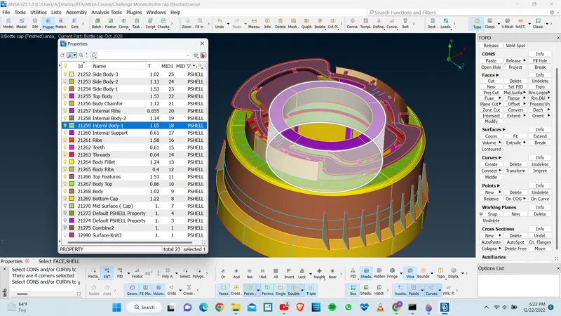
Based on the different thickness of different sections we can assign PID to them.
Activating the materials Card.
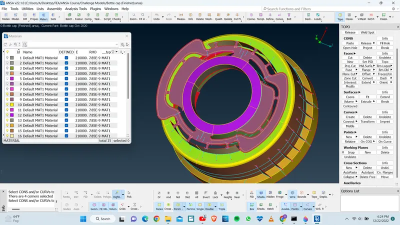
After mid surface extraction, PID allocation and materail card activation we can move towards the meshing section.
3. Meshing
3(a). Defining the given quality criteria -
Given Quality criteria -
| S.No | Quality Criteria | Value |
| 1 | Target/Average length | 1 |
| 2 | Minimum Length | 0.5 |
| 3 | Maximum Length | 3 |
| 4 | Aspect | 3 |
| 5 | Warpage | 15 |
| 6 | Skewness | 45 |
| 7 | Jacobian | 0.7 |
| 8 | Maximum Quad Angle | 135 |
| 9 | Minimum Quad Angle | 45 |
| 10 | Maximum Trai Angle | 120 |
| 11 | Minimum Trai Angle | 30 |
| 12 | Trai Percentage | 15 |
For activting the quality card we need to go to the quality panel in the task bar,
or we can use the shortcut Fn+F11 (Shortcut Key)
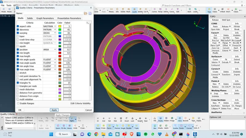
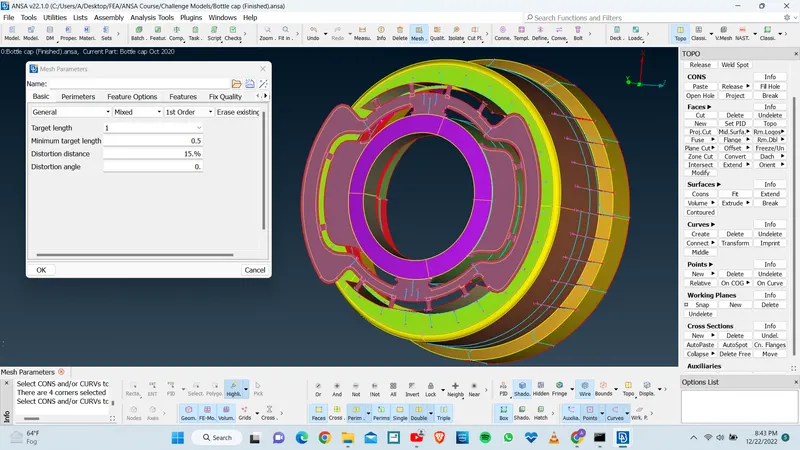
Then setting up the mesh parameters in the mesh pallete.
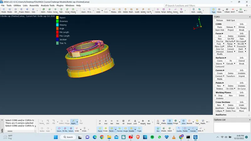
Project cuts are made on model at different sections, which helps ANSA in uniform distribution of mess flow.
Since, now we can proceed for mess module operatons for each components and features independently.
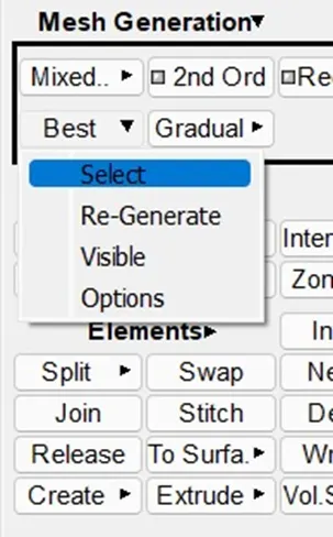
We prefer the Best Mesh alogorithm for meshing.
Mess improvement tool, such as RECONSTRUCT, RESHAPE, SMOOTH, FIX QUALITY are powerful mess generation tools in less duration of time.
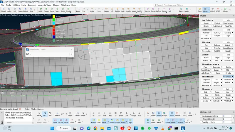
Similarly, we can generate mess on each and every mid surfaces features separately to obtain better and uniform mess flow.
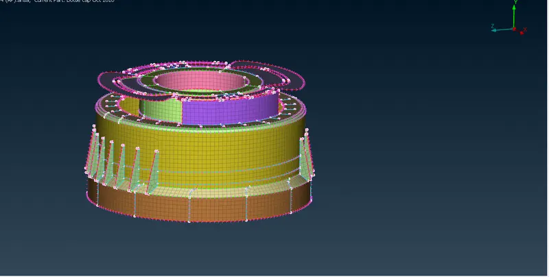
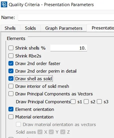
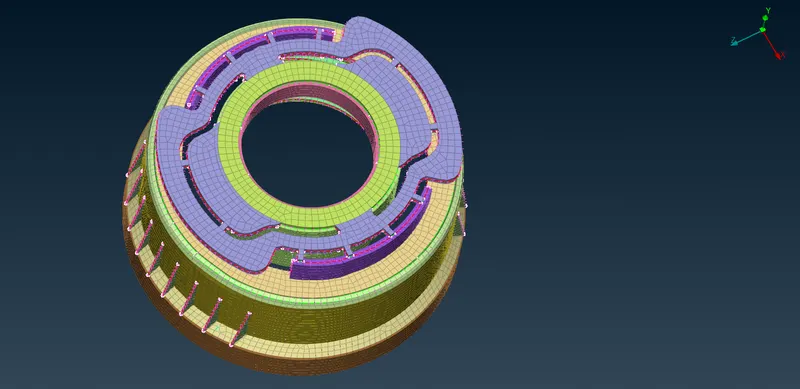
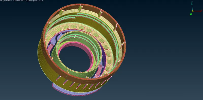
From Quality criteria tab we can apply on Draw shell as solid to visualize assigned thickness of each mid plane of cad model.
Learning outcome -
1. Learn the basic approach to exract the mid surface of complex pastic parts.
2. Gain knowledge of extracting mid of complex plastic parts.
3. Techniques learned to extract mid of critical features like threads, teeth etc.
4. Assigning PID based on thickness in same components.
5. Learn better and smart application of various commands in the ANSA.
Conclusion -
1.Hence we can conclude that the given part is meshed as per given quality criteria following the standard & best practicies.
2.Some Elements near critical features unable to pass the quality criteria.