Week - 4 - 2D meshing for Plastic components
AIM: - MESH THE GIVEN PLASTIC BOTTLE CAP MODEL ACCORDING TO THE GIVEN QUALITY CRITERIA SETTINGS
Objectives:
Check the model for geometrical errors.
Obtain the mid-surface of the model.
Mesh the mid-surface according to the given quality criteria.
Assign PID and thickness to the mesh.
The given challenge was completed using ANSA pre-processing tool, the steps taken for the completion are as follows:
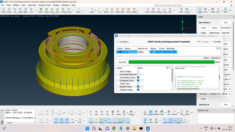
STEP 1: Import the model into the ANSA environment and check the model whether any geometrical error is present in the parent geometry, as shown below:
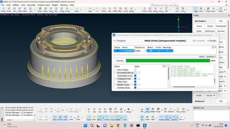
The model is free from geometrical errors and can be used to obtain the mid-surface.
STEP 2: Generating Mid-surface.
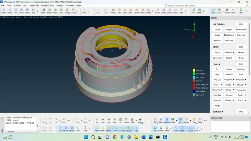
The given geometry is a plastic body; therefore, the thickness is not uniform and, in such cases, the mid-surface can be obtained through the manual process.
The manual process includes operations like Offsetting faces; generating mid-surface using Middle command and pasting the surfaces at the appropriate locations.
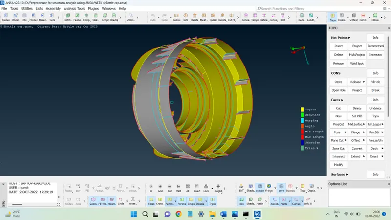
The Mid-surface for the given model is shown in the figure below:
STEP 3: Meshing the mid-surface.
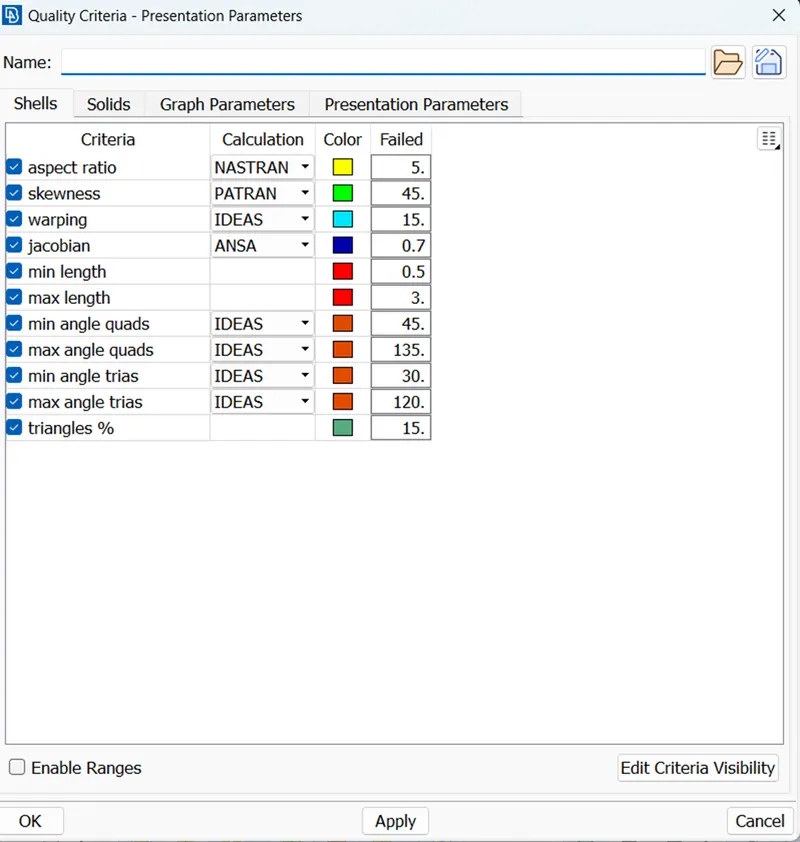
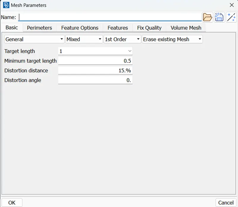
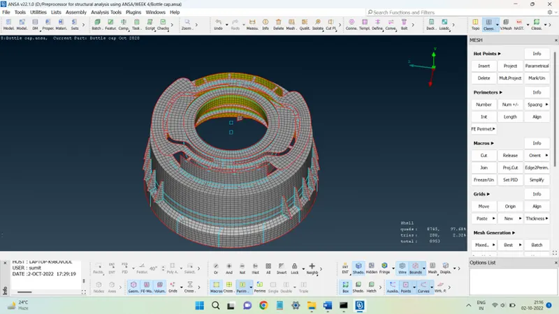
The mid-surface obtained was meshed according to the quality criteria settings mentioned in the below figures:
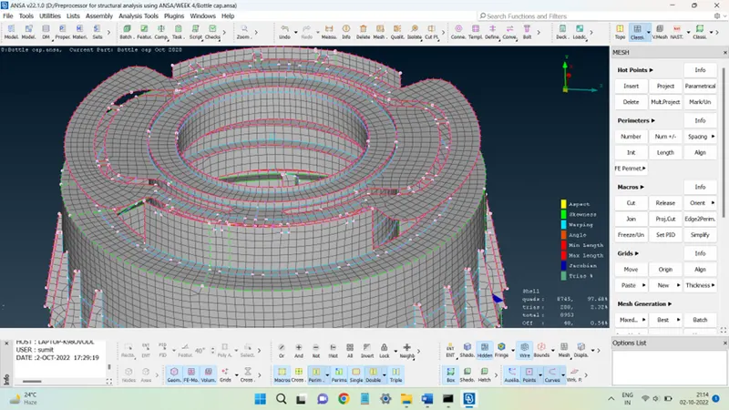
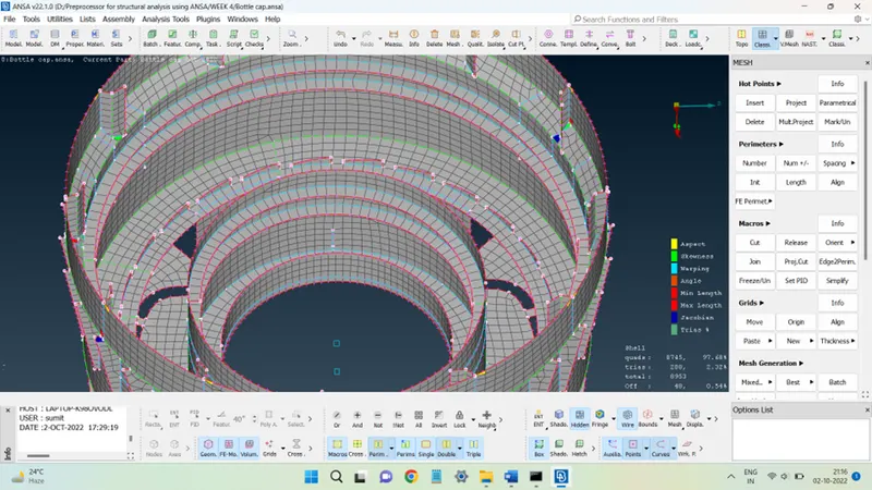
The mesh obtained is shown in the figures below:
STEP 4: Quality checks.
The mesh obtained must follow the quality criteria settings as well as the normals of all the elements must be pointing in the same direction and the mesh should be free from cracks or free edges within the element region.
The results of these quality checks can be seen in the figures below:
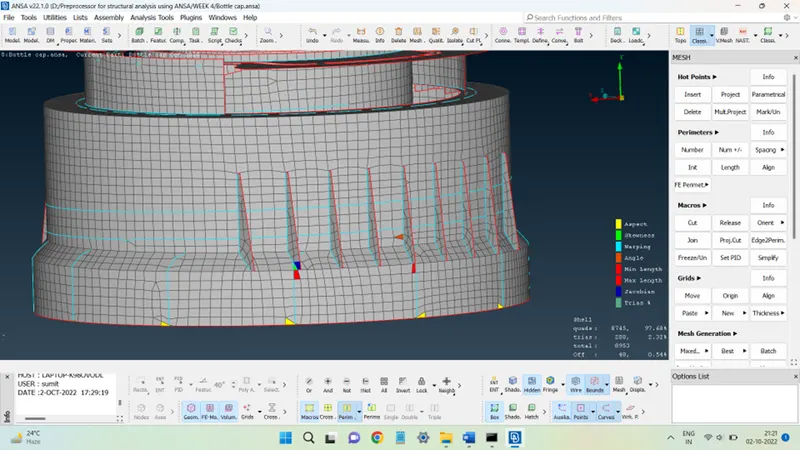
Since the surfaces have complicated connections, there are some failing elements present in the mesh which are unavoidable as seen in the above figure, thus the mesh is obtained such that these elements are as low as possible.
The presence of free edges is checked using the Bounds command if any two elements are not connected then the bounds command highlights that crack through the red color closed curve. If not, the red curve will only capture the surface boundaries.
The below figure shows the mesh viewed with Bounds activated and rest perimeter highlights off. There are no curves seen within the mesh, so it can be said with surety that there are no free edges present in it.
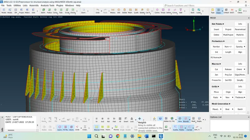
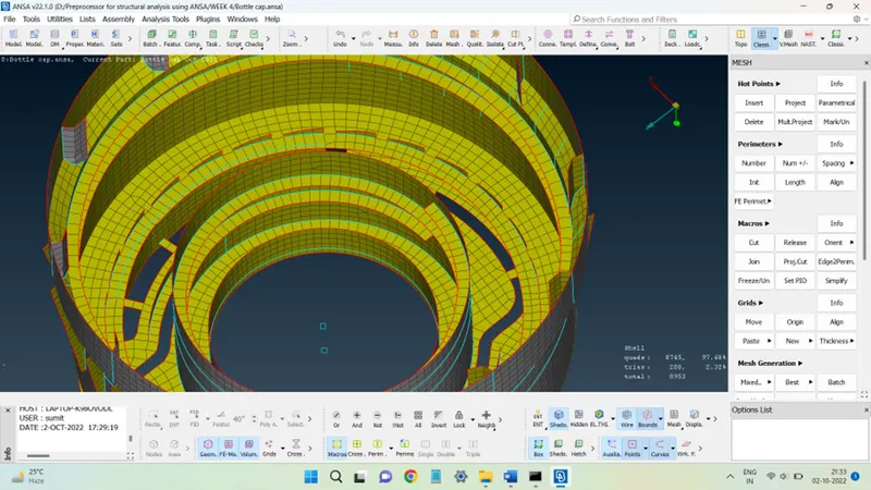
Also, in the above figures, all the elements have gray color on one side and yellow on the opposite side signifying that the normals are also aligned correctly.
STEP 5: Assigning PID and thickness to the elements.
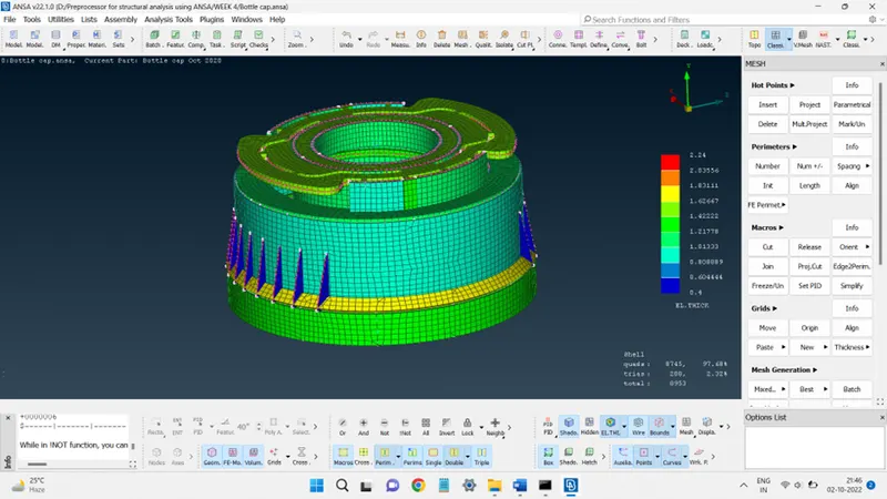
Since the thickness of parent geometry was not uniform, therefore, elements must be assigned the correct consistency. This was done by segregating the different surfaces of the mid-surface according to their thickness and storing them in different Property IDs, as shown below:
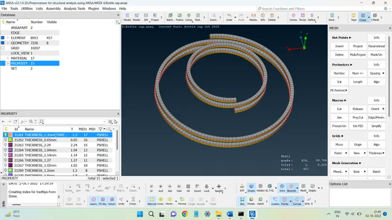
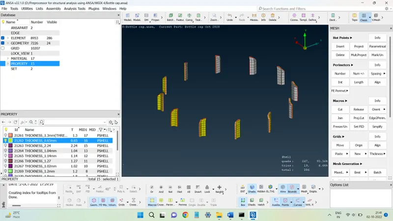
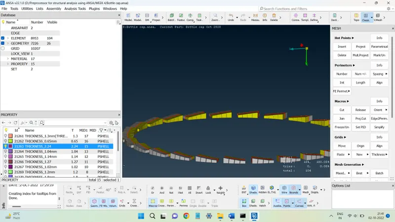
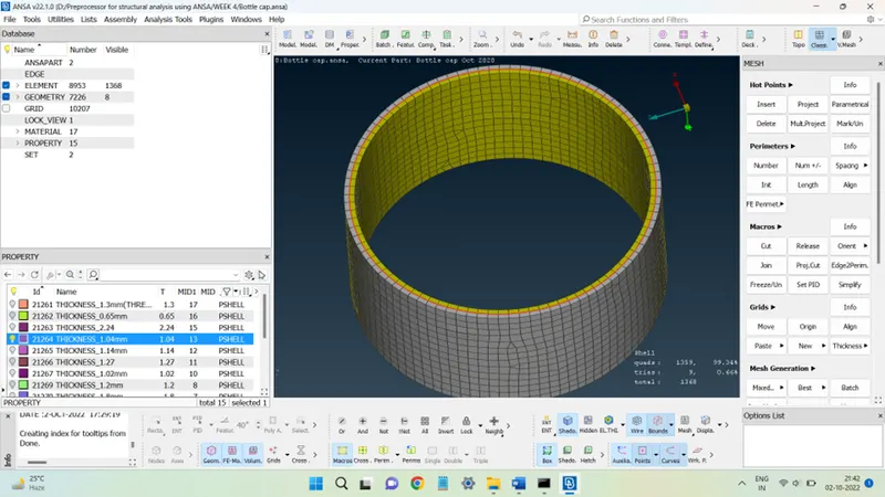
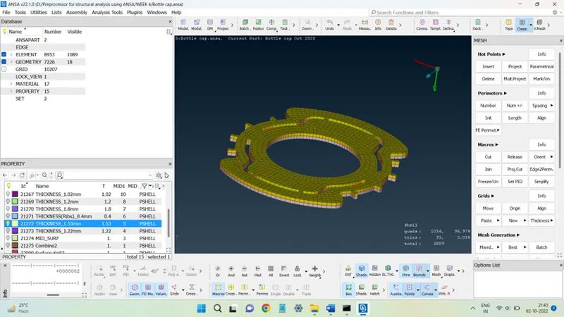
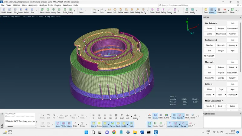
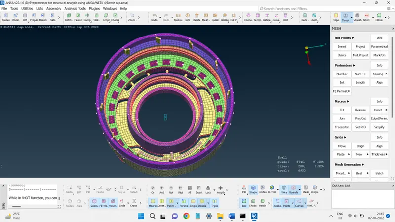
The mesh in the PID view can be seen in the figures below.
Conclusion:
The given model was successfully mid-surfaced and meshed. the thickness was correctly assigned to the respective elements.
This challenge provides the opportunity to learn to mesh plastic geometries with varying thicknesses. Also, how to add different thicknesses to different elements.