Week - 4
1) Aim
-->To implement control logic of a “washing machine” using Stateflow as per below condition
- If the power supply is available, the system gets activated
- If the Water supply is not available, stop the process & indicate through LED
- Soaking time should be 200s followed by Washing time of 100s.
- Then rinsing happens for next 20s & dryer runs for 50s
- After all the processes have completed turn on the finished LED
NOTE:
* The washing machine is operated in electro machanical
*Electronic controllers are used to switch the signals for the corresponding operation.
*The function operates as below:
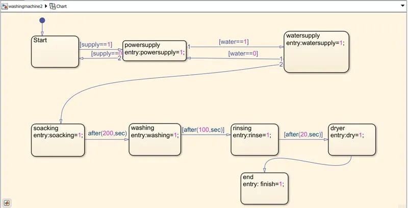
Step 1: Power ON
Step 2: If water flow is present proceed step 3 , If no water flow Switch OFF the unit
Step 3: Water fills the drum till the limit with the electronic controls signal and when water reaches the limit water IN command will cut OFF
Step 4: Fill the cloths in the drum as per the limit (Kg) and add the ditergent and close the machine
Step 5: Soaking operation will take place as per the time interval which is controlled using the controllers
Step 6: After the soaking process, Washing process will take place till the fixed time
Step 7: After the washing process is completed , Rinsing of water will be processed
Step 8: Drying of cloths will be performed when the complete water is rinsed
Step 9: When complete operation is completed a busser sound is given as a command of finish
Controlling operation of machine using state flow:
*Using CHART the controll operation will be performed
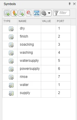
*The input command ON & OFF is given by 0 or 1
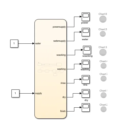
*The outpurt is viewed in display or by Lamp
State flow of machine:
Symbols pane:
Simulink Model:
NOTE:
The lamp will glow in green when the specific operation is processed

*************************************************************************************************************************************
Aim:
-->To make a Simulink chart for the “Gear shift” logic as per below conditions:
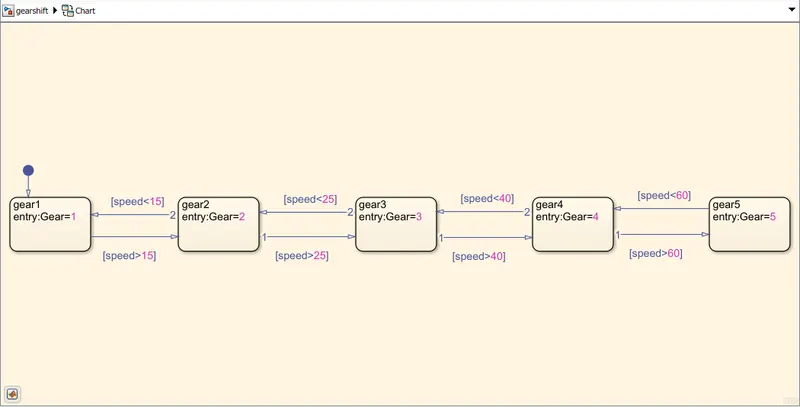
Speed Range(kmph) Gear
0 to 15 1
16 to 25 2
26 to 40 3
41 to 60 4
Above 61 5
Controlling operation of machine using state flow:
*Using CHART the controll operation will be performed
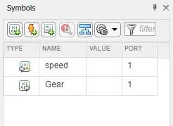
* Speed is determined as input command
*Gear is determined as output command
NOTE:
According to the increase or decrease in speed the shifting of gear is taken place
State flow of gear shift:
Symbols pane:
Simulink Model:
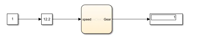
NOTE:
Here to increase and decrease the speed Slider Gain is used
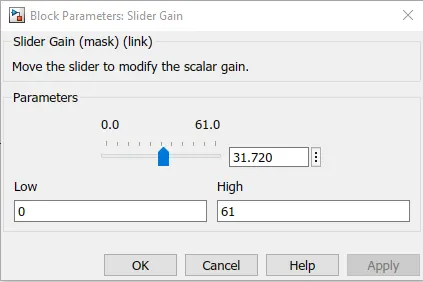
Min & Max kmph is mentioned in Low and High section
Condition 1:
When speed is from 0 - 1 (kmph) gear will be in 1
Condition 2:
When speed is from 16 - 25 (kmph) gear will be in 2

Condition 3:
When speed is from 26 - 40 (kmph) gear will be in 3

Condition 4:
When speed is from 41 - 60 (kmph) gear will be in 4

Condition 5:
When speed is from 41 - 60 (kmph) gear will be in 5

**************************************************************************************************************************************