Introduction:
Burning of fuel to extract work and heat has been used since time era. However, the process has evolved to improve the
efficiency and amount of heat or work extracted.
As many industries today rely on natural gas combustion it becomes necessary for industries to re-use the exhaust gases
to improve heating efficiency and to lower the operating costs. Figure shows a generic process flow used in industries.
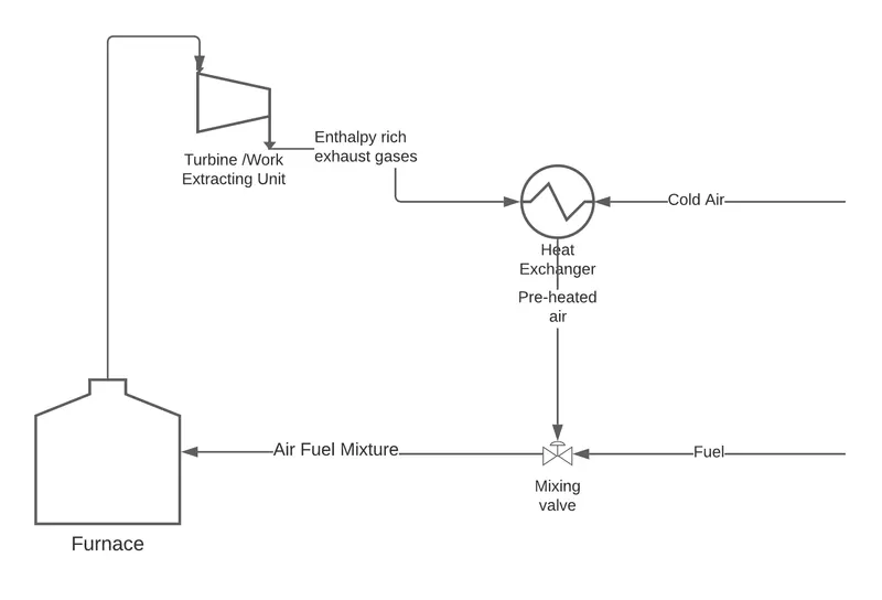
As the gases coming out of turbine or work/heat extracting device at high temperatures are enthalpy rich, they can be
further treated before being led out of the system. Also, if an industry is relying on an expensive and limited fuel it
becomes imperative for them to have maximum heat gain per unit fuel burnt. To facilitate the heat transfer from the
exhaust gases a recuperator is introduced in the process flow of the industry.
A recuperator is a special purpose counter flow heat exchange device kept between exhaust gases and supply of system in
order to recover waste heat. Based on design considerations, type of heat transfer, types of fluids involved and
industrial application various types of recuperators are available. One of the most important consideration while
considering a recuperator is temperature limitation and this is governed by recuperator metal temperature. The metal
temperature can be represented by:
`t_p = (h_g * t_g + h_a * t_a)/ (h_g + h_a)`
For cases when convection recuperator is used `h_g` & `h_a` often becomes equal and hence metal temperature would be
half between air and gas temperature. For a recuperator to provide max heat transfer, it should give the highest
pre-heat at lowest cost and should operate at various temperature range. However, like any other device recuperator
also, cannot be 100% efficient. And as many variables govern the operating conditions of recuperator it becomes very
difficult to assess the optimum or ideal operating conditions.
Below we will try to assess the effect of preheat on adiabatic flame temperature(scenario 1) in hydrocarbon combustion
process along with effect on fuel savings and efficiency gain(scenario 2).
The combustion equation is represented as
`phi < 1`
`phiCH4 + 2(O2 + 3.76N2) -> phiCO2 + 2phiH2O + 2(1-phi)O2 + 7.52 * N2`
`phi > 1`
`phiCH4 + 2(O2 + 3.76N2) -> CO2 + 2H2O + 2(phi - 1)CH4 + 7.52 * N2`
`phi = 1`
`CH4 + 2(O2 + 3.76N2) -> CO2 + 2H2O + 7.52 * N2`
For calculating efficiency gain, following formula is used:
`eta = (Q_(Output)/Q_(Input)) * 100`
Using energy balance above equation becomes
`eta = 100 * (m_a * h_a + h_f * m_f - (m_f + m_a) * h_e) / (m_f * LHV)`
`eta = 100 * (H_a + H_f - H_e)/(m_f * LHV)`
Coding approach:
To observe the above mentioned changes Cantera python library in used. Utility function preheat_effect_on_aft uses
a Solution object to calculate the adiabatic flame temperature of fuel and air mixture over varying range of input
temperature. The results are collected in a python list for further analysis and plotting. Similarly, function
preheat_effect_on_efficiency also uses a Solution object to calculate the gain in efficiency. The results
from above functions are used to plot respective plots against varying temperature.
Constant values and assumptions:
* Temperature Range = `298K` to `600K`
* LHV = 50MJ/kg
* Furnace Exit Temperature = `1700K`
* Constant Pressure reaction
* `phi= 1` for calculating effect of pre-heat on efficiency gain.
Code:
import cantera as ct
import matplotlib.pyplot as plt
from datetime import datetime
import os


def preheat_effect_on_aft(common_gas_object, temperature_variation):
    aft_variation = list()
    # Fuel Quantity object
    fuel = ct.Quantity(common_gas_object)
    fuel.TPX = temp_start, ct.one_atm, {"CH4": 1}
    fuel.moles = 1

    for temp_val in temperature_variation:
        # Air Quantity object
        oxidiser = ct.Quantity(common_gas_object)
        oxidiser.TPX = temp_val, ct.one_atm, {"O2": 0.21, "N2": 0.79}
        oxidiser.moles = 9.52

        # Creating a mixture
        mixture = oxidiser + fuel
        mixture.equilibrate("HP")

        aft = mixture.T
        aft_variation.append(aft)
    return aft_variation


def preheat_effect_on_efficiency(common_gas_object, temperature_variation, furnace_exit_temp):
    gain_in_efficiency = list()
    try:
        base_temperature = temperature_variation[0]
    except IndexError as IE:
        base_temperature = 298
        print(IE)

    # Fuel Quantity object
    fuel = ct.Quantity(common_gas_object)
    fuel.TPX = base_temperature, ct.one_atm, {"CH4": 1}
    fuel.moles = 1

    for temp_val in temperature_variation:
        # Air(Preheated) Quantity object
        oxidiser = ct.Quantity(common_gas_object)
        oxidiser.TPX = temp_val, ct.one_atm, {"O2": 0.21, "N2": 0.79}
        oxidiser.moles = 9.52

        # Creating a mixture
        mixture = ct.Quantity(common_gas_object)
        mixture.TPX = furnace_exit_temp, ct.one_atm, {"CO2": 0.095, "H2O": 0.1901, "N2": 0.7148}
        mixture.moles = oxidiser.moles + fuel.moles

        # Mass of fuel
        mass_of_fuel = fuel.mass

        gain = 100 * ((oxidiser.enthalpy + fuel.enthalpy - mixture.enthalpy) / (mass_of_fuel * LHV))
        gain = round(gain, 2)
        gain_in_efficiency.append(gain)
    return gain_in_efficiency


def plot_data(x, y, x_label, y_label, plot_title, image_name, image_location, save_image=False, **kwargs):
    plt.figure()
    plt.xlabel(x_label)
    plt.ylabel(y_label)
    plt.title(plot_title)
    plt.tight_layout()
    plt.grid()
    plt.plot(x, y)
    if save_image:
        image_name = f"{image_name}.png"
        image_location = os.path.join(image_location, image_name)
        plt.savefig(image_location, dpi=300, **kwargs)
    plt.show()


if __name__ == "__main__":
    date_time_stamp = datetime.now().strftime("%Y%M%d_%H%M%S")
    temp_start, temp_end = 298, 601
    temperature_range = range(temp_start, temp_end)
    LHV = 5e7
    assumed_furnace_exit_temp = 1700  # K
    scenario1, scenario2 = "PreHeatEffectAFT", "EfficiencyGain"

    gas = ct.Solution("gri30.cti")
    results_dir = os.path.join(os.getcwd(), "results")
    if not os.path.exists(results_dir):
        os.mkdir(results_dir)
    change_in_aft = preheat_effect_on_aft(gas, temperature_range)
    gain_in_eff = preheat_effect_on_efficiency(gas, temperature_range, assumed_furnace_exit_temp)
    normal_eff = preheat_effect_on_efficiency(gas, temperature_range, 298)

    plot_data(temperature_range,
              change_in_aft,
              "Intake temperature variation(in K)",
              "Variation in AFT(in K)",
              scenario1,
              f"{scenario1}_{date_time_stamp}",
              results_dir,
              save_image=True)
    plot_data(temperature_range,
              gain_in_eff,
              "Intake temperature variation(in K)",
              "Gain in efficiency(in %)",
              scenario2,
              f"{scenario2}_{date_time_stamp}",
              results_dir,
              save_image=True)
Results:
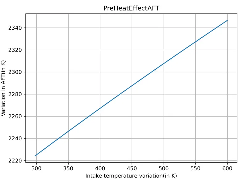
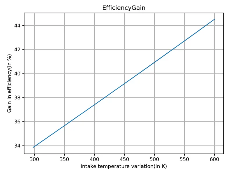
* From the above graph we can observe there is positive trend in adiabatic temperature when the intake temperature
increases.For every 50K rise in intake temperature, the AFT rises by approx 21K. Hence,for given constant pressure,
constant air fuel ratio, a higher intake temperature results in higher AFT and thus a higher intake temperature is preferred.
* In efficiency gain vs intake temperature graph also, we can observe a similar positive trend. For every 50K rise in
intake temperature efficiency gains by approx 1.8%. Hence, for a given set of constant conditions, the efficiency
increases as temperature increases. This further helps in improving fuel saving as the same amount of fuel is used to
calculate the efficency at varying intake temperatures.
* It can be observed that the furnace exit temperature was assumed as 1700K(`1404^circC`). In industry, it is observed that
with higher exit temperatures formation of iron oxide scales on recuperator tubes takes place. This not only affects
the life of recuperator but also adversely affects optimum working as the heat distribution is affected.As mentioned
recuperator consideration is governed by maximum metal temperature(`1050^circC` for convection type recuperators and `1500^circC`
for radiation type recuperators). Hence, the exhaust air coming out of furnace has to be controlled so that the
recuperator can be operated under its standard operating conditions to avoid any safety related hazards of recuperator
and components attached to it.This also ensures that the recuperator and its components like recuperator tubes has a
extended life.