Week 4-1D Element Creation Challenge
Mid-surface meshing and 1D connectors
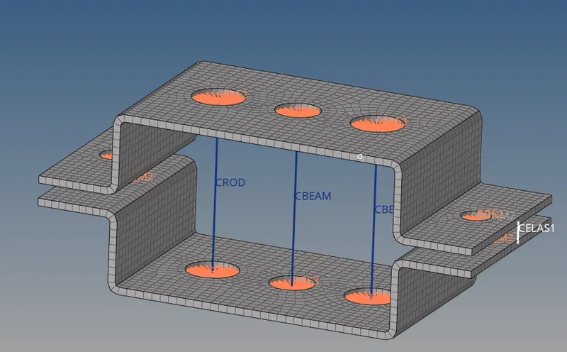
Objective: To extract and mesh the mid-surface of the given bracket and generate 1D elements connecting the two halves of the bracket.
Geometry: The given part is a bracket with an upper and lower half. The overall length and width of the part are 300mm and 125mm respectively. Additionally, it has two holes of 35mm dia and one hole of 30mm dia on each of the longer surfaces, and one hole of 20mm on each half of the shorter surfaces.
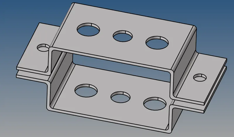
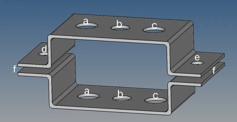
Fig1: Part geometry with labeled pinholes
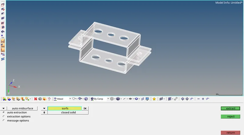
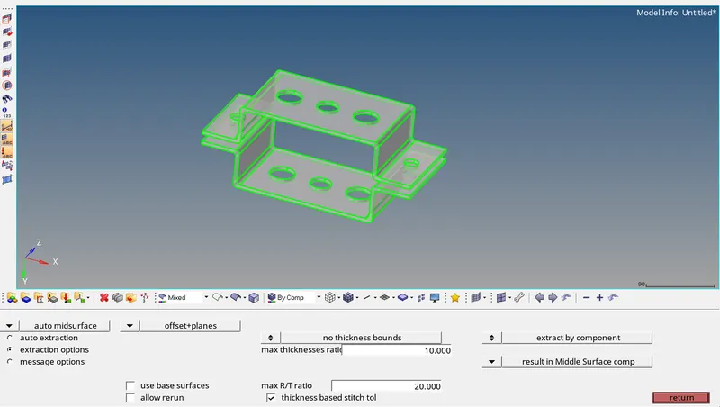
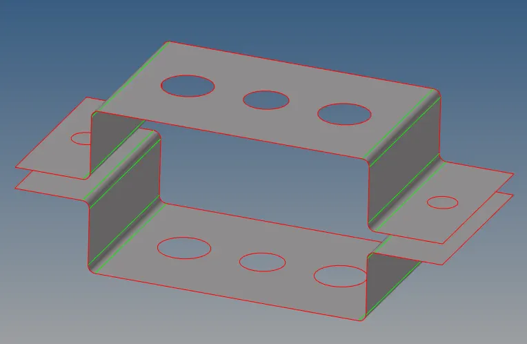
Mid-Surface Extraction: The mid-surface is extracted using Geom>midsurface>auto midsurface. The extraction option is set to "Offset+planes" to extract the fillets accurately. For the sake of this exercise, the fillets were not defeatured from the model. The resulting midsurface is as shown below.
Meshing: Washer splits of 5mm offset were created around the holes. The surface was meshed with a target element size of 5mm with mixed - quad and tria first-order elements. Apart from equalizing the number of elements around the washer splits, no major changes were made to the mesh as the quality of the mesh was not of much importance in this exercise.
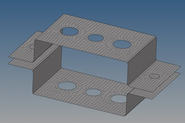
A property card for the 2D mesh is created and the card image of PSHELL is assigned to it along with a thickness of 5mm.
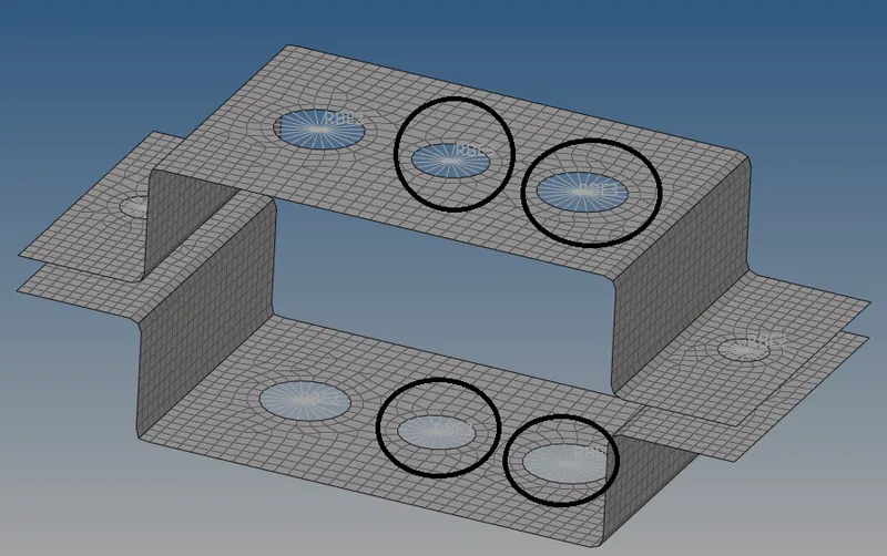
Rigids: For the holes labeled 'a' in Fig1, RBE2 rigid body were created with the nodes around the inner circle of the washer split using 1D>rigids. Translational degrees of freedom dof1, dof2, dof3 were constrained. Similar rbe2 elements were created for the 20mm dia holes 'd' and 'e' as well with the exception that all its dofs were constrained.
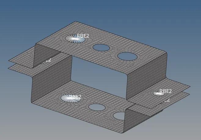
For the holes labeled 'b' rbe3 rigid body was created using 1D>rbe3 with all DOFs constrained. Similarly rbe3 rigid was created for holes 'c' but with the z-direction dofs free i.e. dof5 and dof6 were free.
Rod: Using 1D>rods, the two center nodes of the rbe2 rigids of holes 'a' were selected to form a CROD 1D connector. The cross-section of the rod was defined in Hyperbeam>standard section>thin-walled box. The dimensions of the box are as shown below.
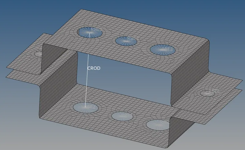
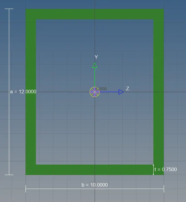
A property card for rod is created with the card image of PROD and the 'box_section' is assigned to its beam section. The rod element is updated.
Beam: Using 1D>bars, the two center nodes of the rbe3 rigids of holes 'b' were selected to form a CBEAM 1D connector. The cross-section of the rod was defined in Hyperbeam>standard section>standard section I. The dimensions of the I section are as shown below.
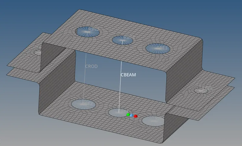
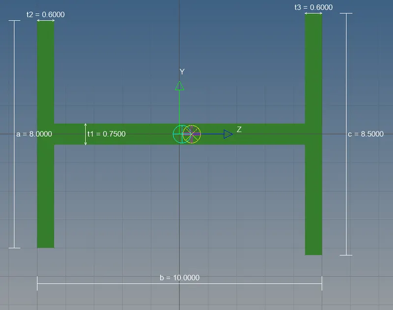
A property card for the beam is created with the card image of PBEAM and the 'I_section' is assigned to its beam section. The beam element is updated.
Bar: Using 1D>bars, the two center nodes of the rbe3 rigids of holes 'c' were selected to form a CBAR 1D connector. The cross-section of the rod was defined in Hyperbeam>standard section>Cross from the OPTISTRUCT library. The dimensions of the X-section are as shown below.
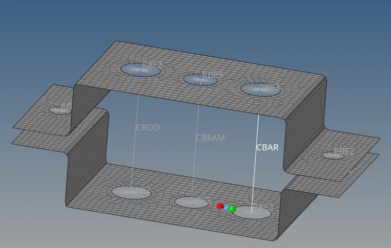
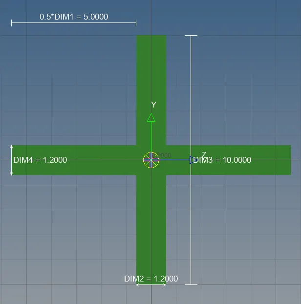
A property card for the bar is created with the card image of PBAR and the 'cross_section' is assigned to its beam section. The bar element is updated.
Mass: A mass of 10kg is applied to the center nodes of rbe2 elements on holes 'd' and 'e' using 1D>masses.
Springs: Two spring elements are created using 1D>springs and selecting one node each from the bottom and top halves of the bracket. CELAS1 type elements are created. The constraint is left to its default setting values.
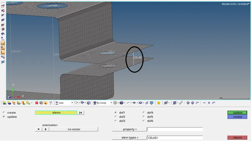
Result: The resultant 2D meshed part with 1D connectors is as shown below:s