Week 4-1D Element Creation Challenge
Aim - Mesh the Given component with the Size of 5 Units. Create 1D elements on the following component with the given cross-section and DOF
Input Data & Conditions -
a. Rod element:- Translational DOF should be Constrained with RBE2 link
Cross-Section: BOX- Dimension a= 12 mm
dimension b=10 mm
Thickness t= 0.75 mm
b. Beam element:- All DOF should be constrained with RBE3 link
Cross-Section: I Section- Dimension a= 8 mm
Dimension b= 10 mm
Dimension c= 8.5 mm
Thickness t1= 0.75 mm
Thickness t2= .6 mm
Thickness t3= .6 mm
c. Bar element:- Constrain only x and y DOFs With RBE3 link
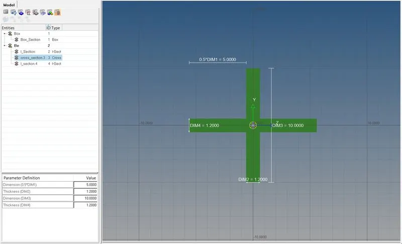
Cross-section: X section- Dimension DIM1= 5 mm
Thickness DIM2= 1.2 mm
Dimension DIM3= 10 mm
Thickness DIM4= 1.2mm
d. & e. Apply the mass of magnitude 10 with the RBE2 link
f. Join the two components with Spring elements
Methodology -
- To Import the component open the hypermesh program and import the solver deck window.
- Select the Import CAD option>select the file to import>Click Import.
- Now we have the desired CAD file for our project.
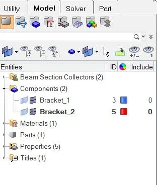
Note - For creating mid surface always create components in hypermesh.
- To create mid-surface open Geom>midsurface>Auto-midsurface>surf>select the component for midsurfacing>create.
- After creating the mid surface delete the solid part.

Repeat the process for creating a mid surface for another component.
- After creating the mid surface use the quick edit tool to create a washer split at the edges of the holes and use auto cleanup before meshing the component.

- Create the mesh of element size 5 using the auto meshing options in the 2D workbench.
- Repeat the process for the 2nd Bracket.
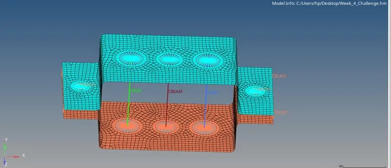
Note - Check the geometry of the component properly before moving ahead.
- For creating the Bar, Beam, and Rod section go to the 1D>hyper beam>Standard sections>Hyperbeam>I section>Create
I section -
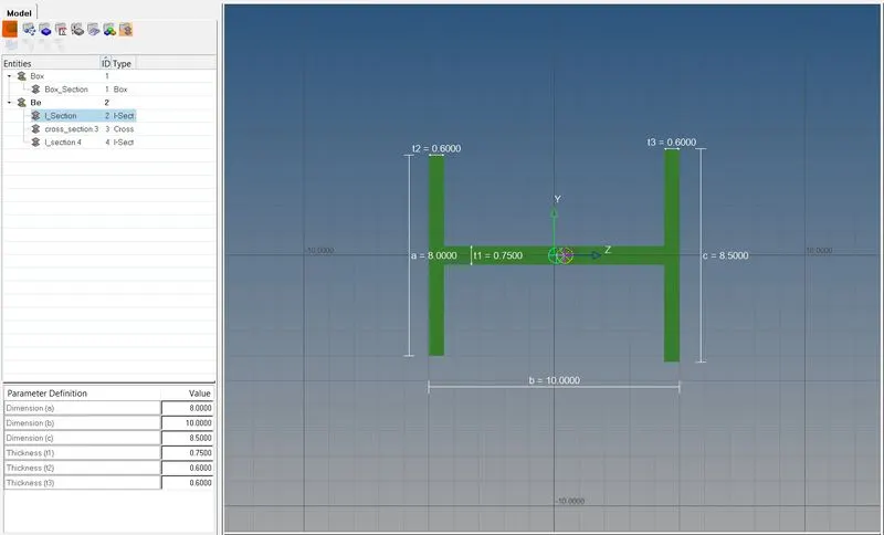
Cross Section -
Box Section -
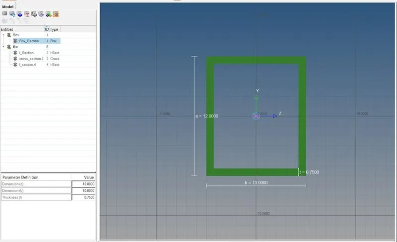
Enter the values provided in the question and open the model viewer.
Repeat the process for all the other sections
Now we will create the RBE2 and RBE3 Elements at the required position as mentioned in the question.
- Open the 1D workbench>select Rigid for RBE2>Select by path> Select the desired nodes and required DOF> Select create.
- Open 1D workbench> select RBE3>Select by path >Select the desired nodes> Select create.
After creating the RBE2 and RBE3 nodes we can now create the properties for Rod,Bar and Beam Elements.
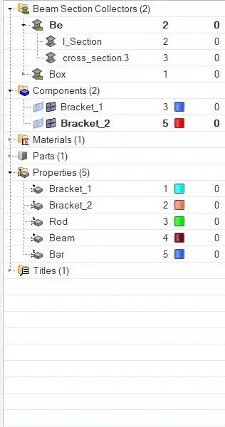
- Right-click on the model>select Create>Select properties>Under card image select(PROD/PBEAM/PBAR)>Select material>Select Cross section>Create.
Repeat the process for all the cross-sections.
now we will Insert the sections in our model.
- Open>1D Workbench>Select>Rods/Beam>Select Nodes>Select properties>Select Element type>Create.


Repeat the process for all elements.
We have now successfully created all the elements in our model.
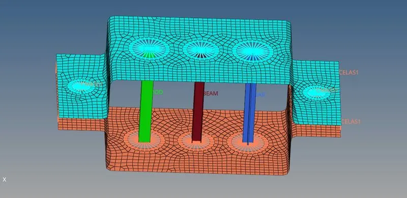
Link of the Model - https://drive.google.com/drive/folders/18bVe-U3v5ATI1IhzrF6LLiNEOithvnw3?usp=sharing