Week 4-1D Element Creation Challenge
AIM: - MESH THE GIVEN COMPONENT WITH THE SIZE OF 5 UNITS AND CREATE THE 1D ELEMENTS ON THE COMPONENT HAVING THE BELOW-MENTIONED CROSS-SECTION AND DOF.
Objectives:
1. Mesh the given component with the size of 5 units.
2. Add the following 1D elements:
a) Rod Element with translational DOF constrained with RBE2 link
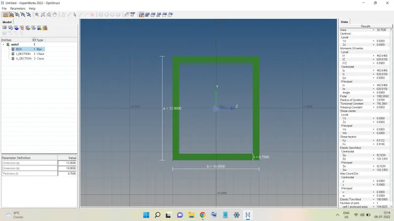
Cross-section = BOX of Dimensions:
a = 12 mm; b = 10 mm; thickness = 0.75 mm.
b) Beam Element with all DOF constrained with RBE3 link
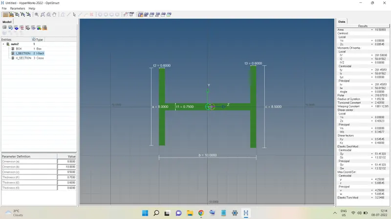
Cross-section = I – section having dimensions as
a = 8 mm; b = 10 mm; c = 8.5 mm
thickness (t1) = 0.75 mm; thickness (t2) = 0.6 mm; thickness (t3) = 0.6 mm.
c) Bar Element with only X and Y DOF with RBE3 link
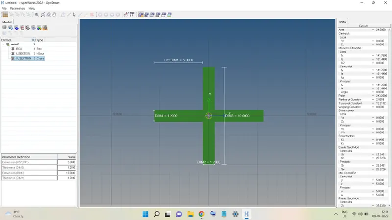
Cross-section = X – section with dimensions as
Dimension DIM1 = 5 mm
Thickness DIM2 = 1.2 mm
Dimension DIM3 = 10 mm
Thickness DIM4 = 1.2 mm
d) & e) Apply the Mass of magnitude 10 with RBE2 link
f) Join the two components with Spring Elements.
The task is completed using the Optistruct profile in the Hypermesh and the following are the steps taken:
STEP 1: the given IGS file is imported into the software, the geometry imported is shown below.
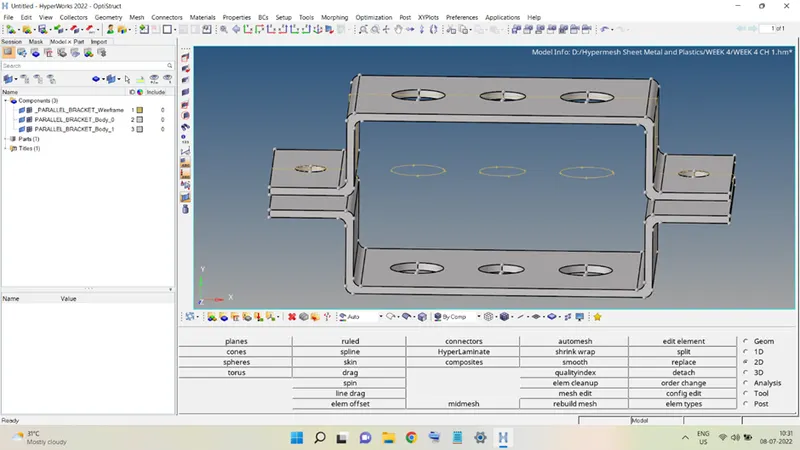
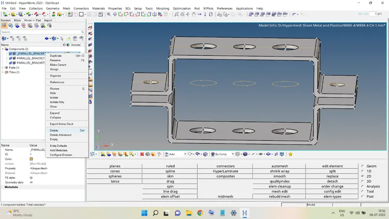
The wireframe component is deleted from the model and the model will be;
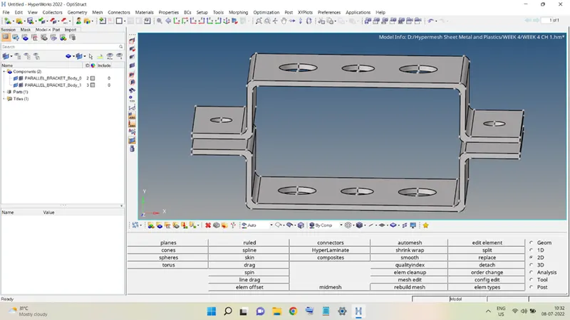
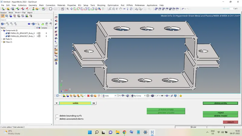
All solid bodies are also deleted.
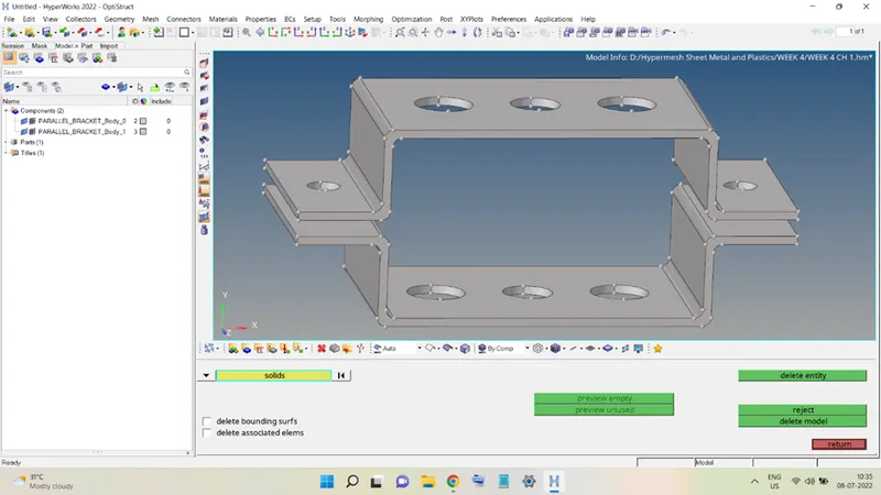
STEP 2: Generating the Mid-Surface for both the components:
The mid-surfaces for each surface were generated one by one and the surfaces look like this:
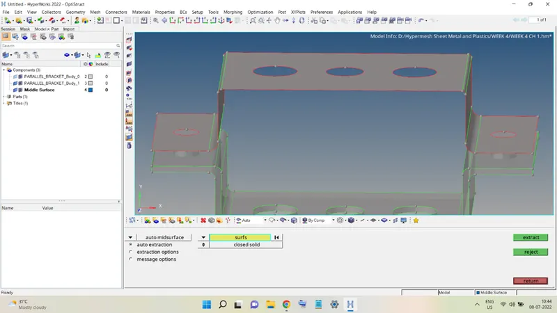
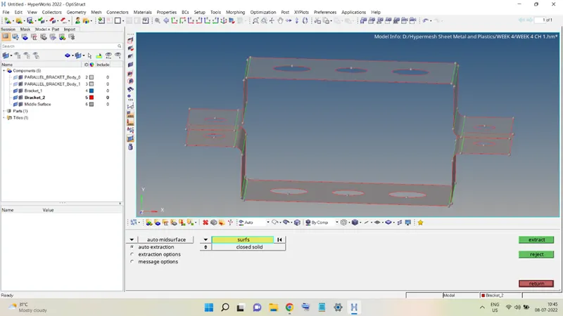
Create the two new components named; Bracket_1 and Bracket_2 before generating the mid surfaces for the respective components, else both the mid-surfaces will be generated as a single component.
The original components are deleted after acquiring both the mid-surfaces.
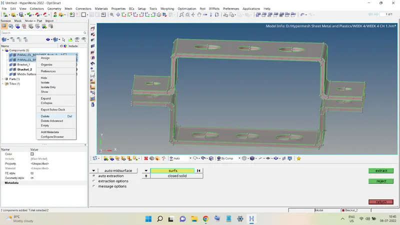
Move the component named Middle Surface to Bracket_2.
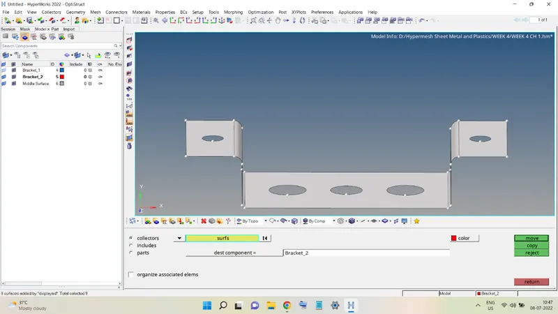
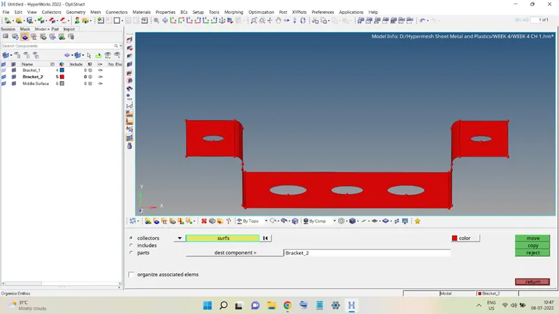
Delete the component Middle Surface, the surfaces generated will look like this:
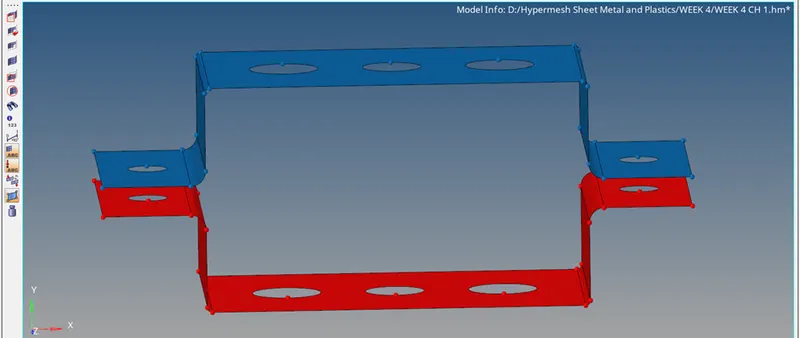
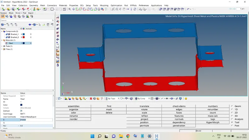
STEP 3: Add Material to the model:
Steel material is added to the model, and the properties associated with the material are shown in the figures below.
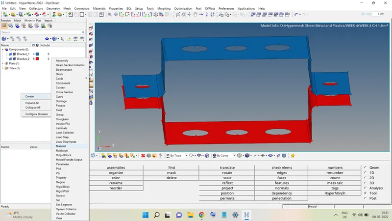
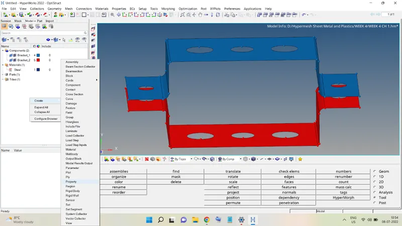
STEP 4: Add Property for the mid-surfaces:
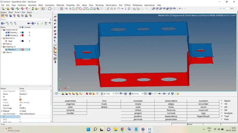
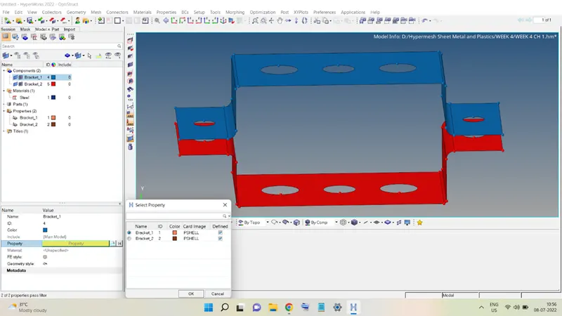
Each mid-surface is supplied with different property. The Property of Bracket_1 included the CARD IMAGE as PSHEEL, Steel as material and Thickness is 2 mm.
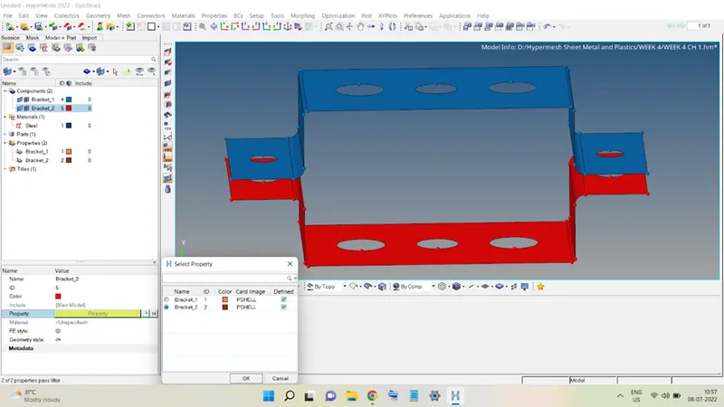
Similarly for the Bracket_2, the CARD IMAGE is PSHEEL, the material is Steel and the Thickness is 2.5 mm.
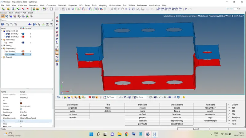
These properties then were added to the respective components:
STEP 5: Adding Washer Split around the holes:
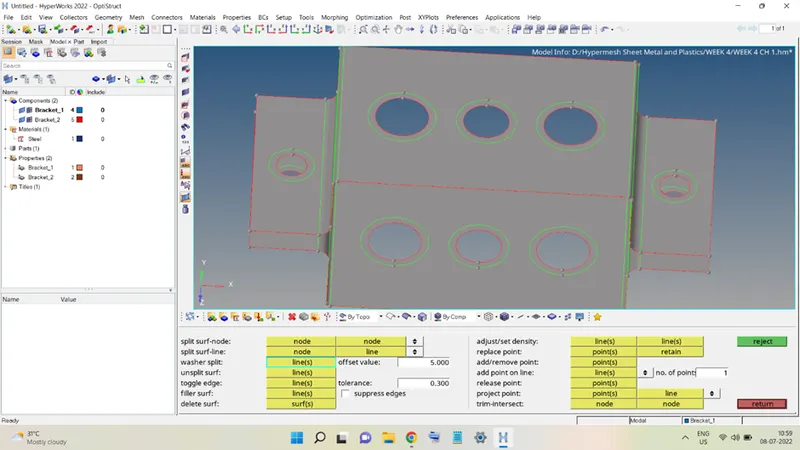
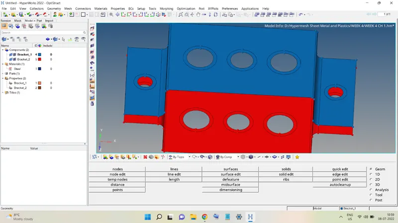
Before the meshing is done, the Washer Split is added around all the holes, and the Offset given to the splits is equal to 5 mm.
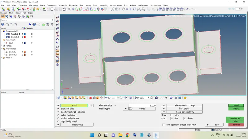
STEP 6: Meshing the surfaces:
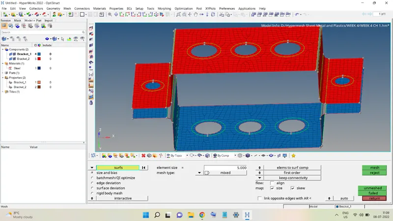
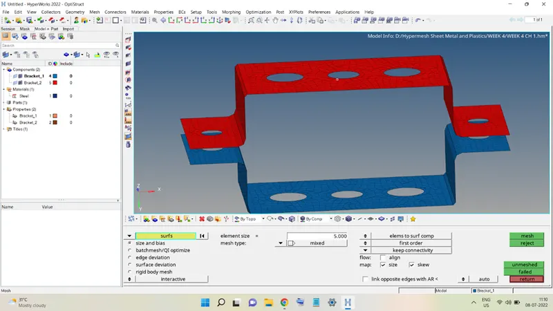
Both the surfaces were meshed with a Mixed element mesh and the Element Size as 5 mm.
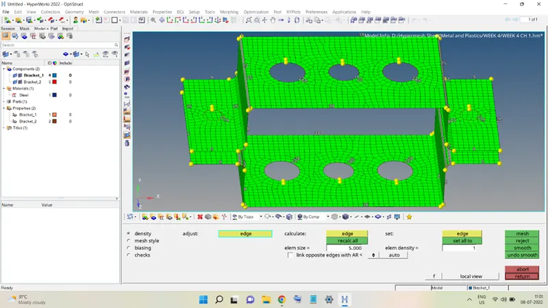
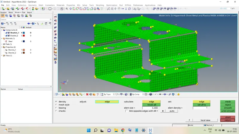
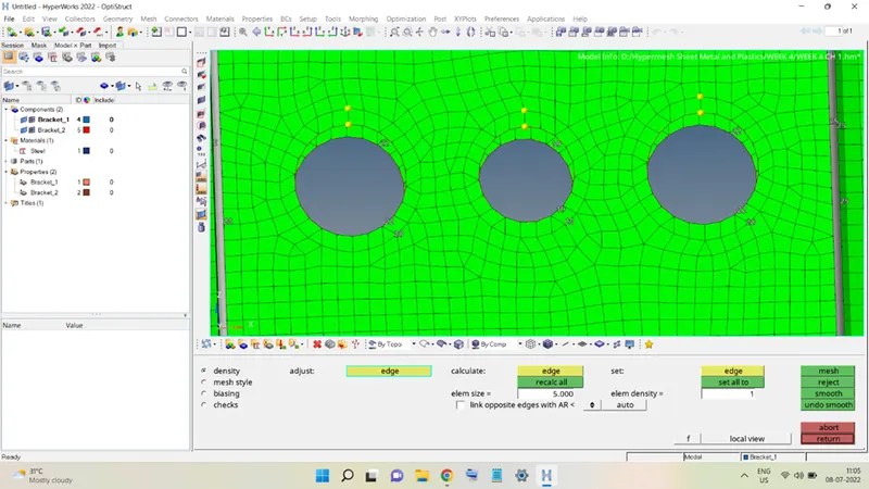
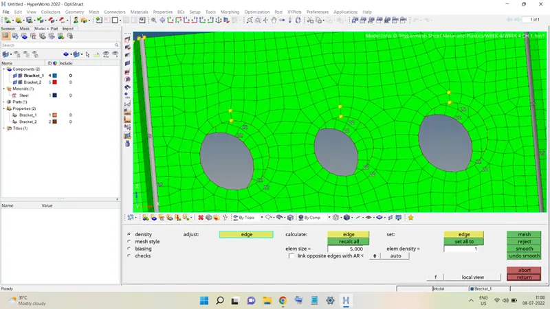
The mesh near the holes is not capturing the profile with the shown number of elements, so the number of elements was altered to capture the profile in a better sense.
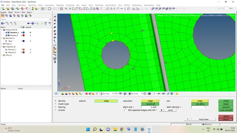
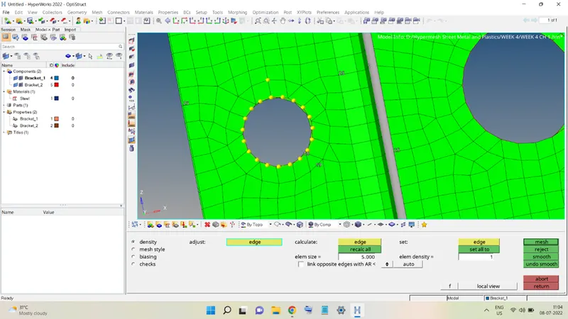
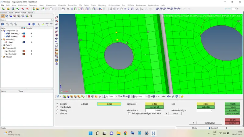
Mesh around the central holes:
The mesh with the geometry surface looks like this:
The mesh without the geometry surface is:
STEP 7: Adding all the required 1D elements in the mesh:
First, the RBE2 links were added around the holes, these links have translational DOF restricted, as shown below:
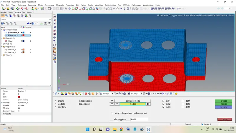
The ROD element is then added between the central nodes of both the links.
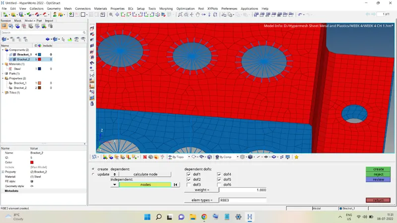
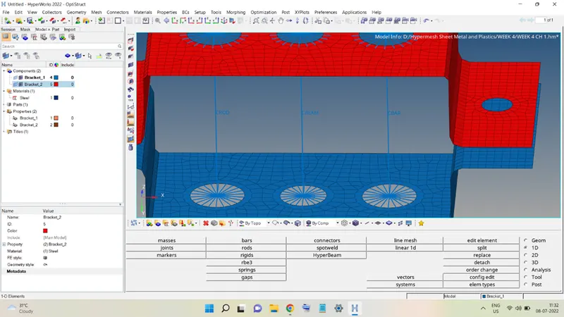
Following the same method, RBE3 links were added next, and then the BEAM element.
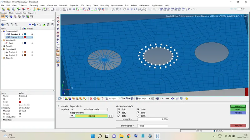
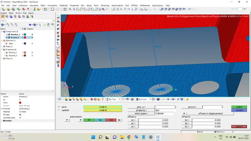
Next, the BAR element is added to the central nodes of the RBE3 links on both surfaces.
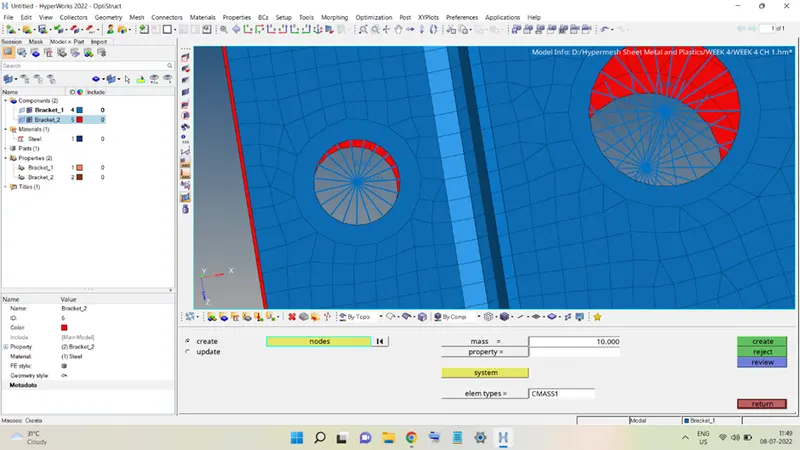
Two RBE2 links were added to the small holes on the Bracket_1 surface and the Mass element having the magnitude of 10 is then added to the central nodes of each of those links.
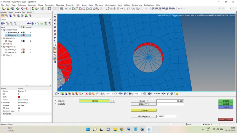
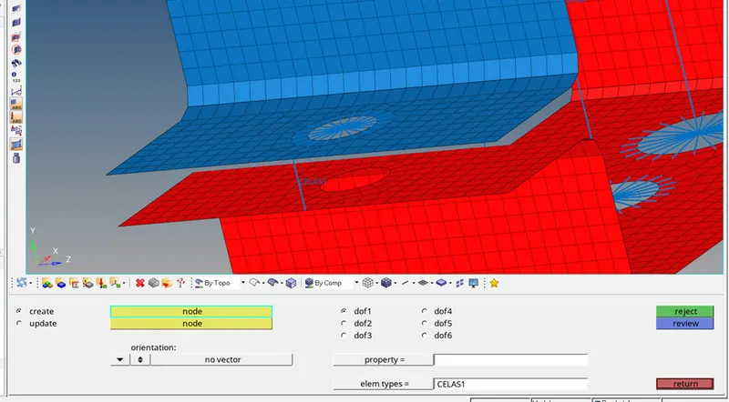
And lastly, the Spring Elements were used to connect both the surfaces, as shown below:
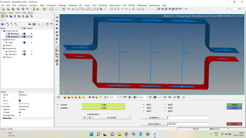
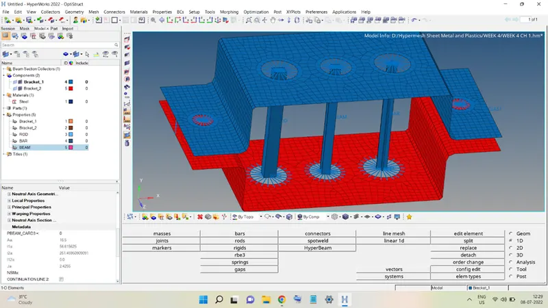
The model after all the elements were successfully added to it looked like this:
STEP 8: Adding the Cross-sections for different elements:
The cross-sections assigned to the respective 1D elements were created with the help of the Hyperbeam tool. Following are the cross-sections, along with the appropriate dimensions, of the different elements:
BOX for the Rod element:
I-SECTION for the Beam element:
X-SECTION for the Bar element:
STEP 9: Adding Properties for the elements and updating those properties into the elements:
For each of the elements a new Property was added to the model, as shown:
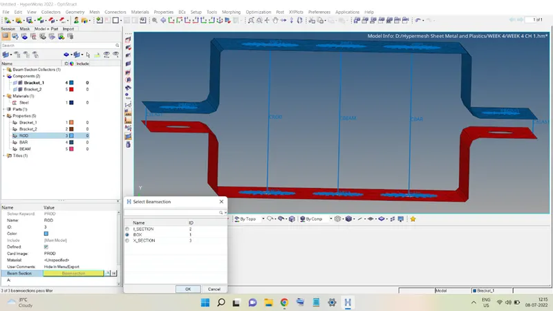
ROD:
PROD is the Card Image for the rod element and the cross-section is the BOX.
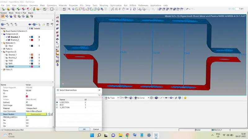
BEAM:
For Beam, the Card Image is PBEAM and the cross-section is I_SECTION.
BAR:
The Card Image is PBAR and the cross-section is X_SECTION.
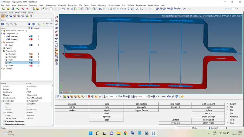
Then the elements are updated with these properties added into the model.
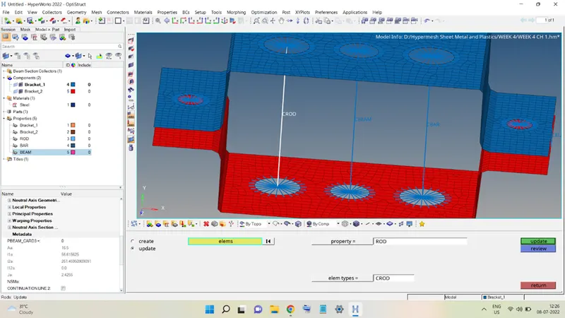
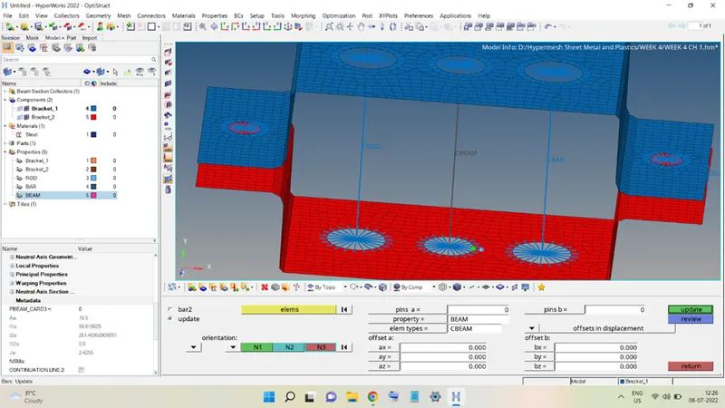
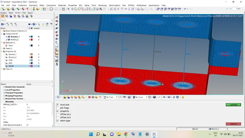
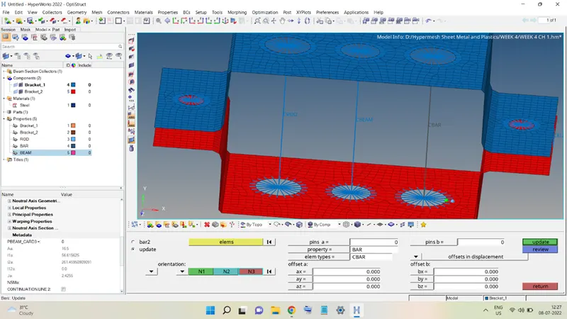
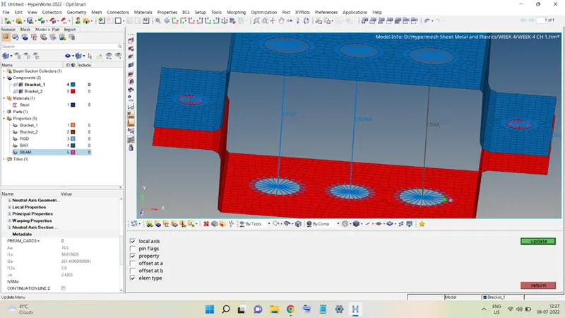
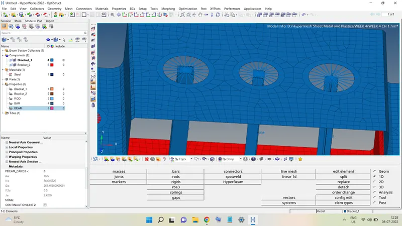
Finally, the model with all the elements and properties added to it will look like this:
conclusion:
the task given was a good way to learn how to:
generate the Mid-surface.
2D mesh a surface.
creating different 1D links.
adding all sorts of 1D elements to the mesh.
adding cross-sections using Hyperbeam.
adding different properties and materials into the model.
updating the elements with newly added properties.