Week 4-1D Element Creation Challenge
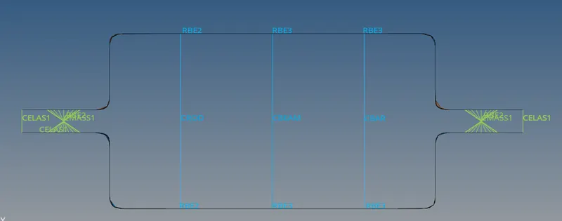
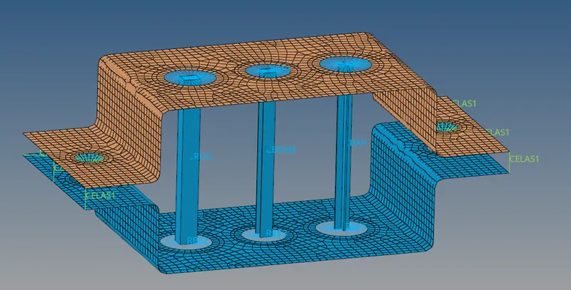
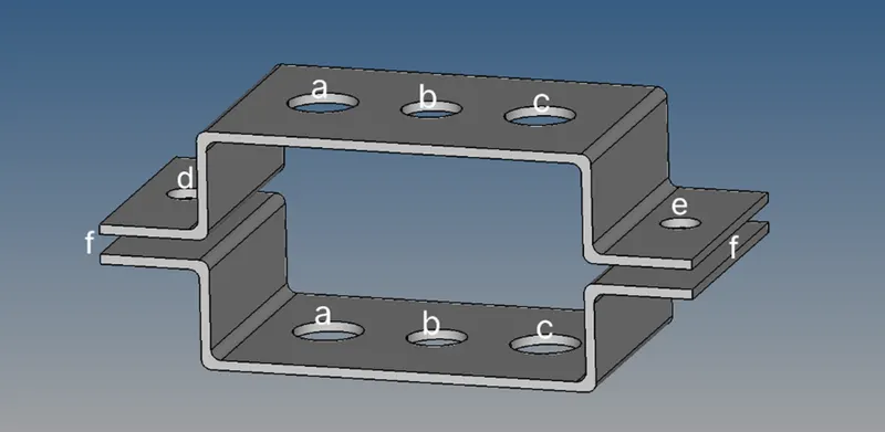
AIM: Mesh the component with the size of 5 units. Create 1D elements on the following component given cross-section and DOF.
OBJECTIVE:
- Rod element:- Translational DOF should be Constrained with RBE2 link
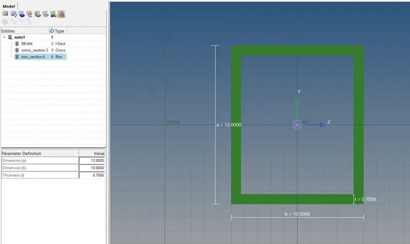
Cross-Section: BOX- Dimension a= 12 mm
Dimension b=10 mm
Thickness t= 0.75 mm
- Beam element:- All DOF should be constrained with RBE3 link
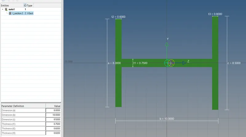
Cross-Section: I Section- Dimension a= 8 mm
Dimension b= 10 mm
Dimension c= 8.5 mm
Thickness t1= 0.75 mm
Thickness t2= .6 mm
Thickness t3= .6 mm
- Bar element:- Constrain only xand y DOFs With RBE3 link
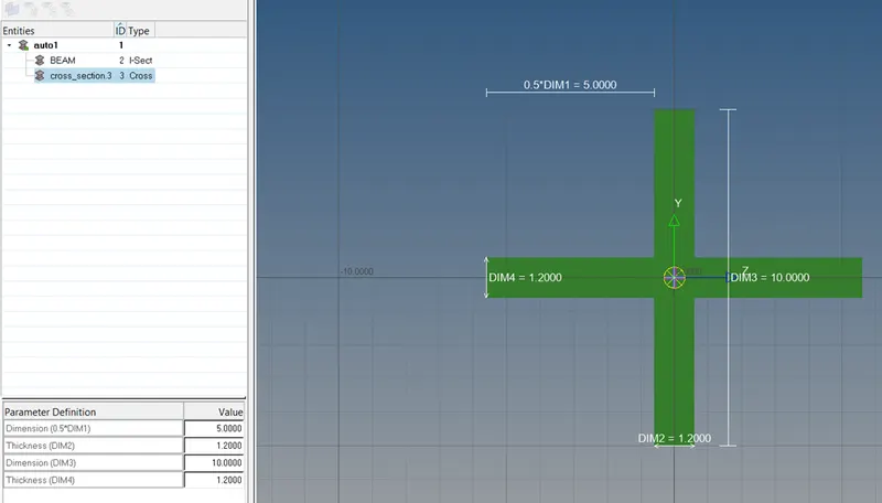
Cross-section: X section- Dimension DIM1= 5 mm
Thickness DIM2= 1.2 mm
Dimension DIM3= 10 mm
Thickness DIM4= 1.2mm
- & e. apply the massof magnitude 10 with the RBE2 link
f. Join the two components with spring elements
PROCEDURE:
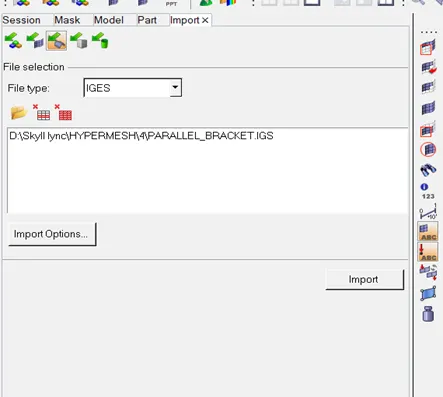
- Firstly we need to import a geometry into a Hyper mesh.
Import solver deck > Import geometry > Select file > Import.
- Then we are going to use auto cleanup.
- After this we need to create midsurface.
Geom > midsurface > surfs > select upper bracket > extract.
Same procedure for the lower bracket.
Tools > Organize > surfs > Select LOW_MIDSURFACE > Move.
- Now delete the component PARALLEL BRACKET_BODY_0 & PARALLEL BRACKET_BODY_1.
- Delete middle surface in the component from the feature tree.
- Now we need to create a material.
- For good mesh we are using washer split.
Geom > Quickedit > Washer Split > Select the circle area > return.
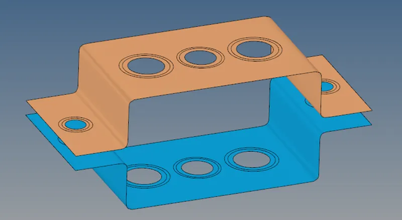
- Now we need to create a 2D mesh.
2D > automesh > element size (5) > Mesh > return.
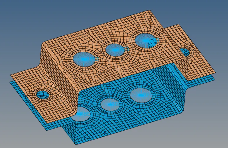
- Now we need to create ROD, BAR, BEAM cross-section according to the problem.
1D > hyperbeam > standard section > standard I section > create > rename it as BEAM.
Entities > create > standard section > optistruct > CROSS > rename it as BAR.
Entities > create > standard section > optistruct > BOX > rename it as ROD.
- According to problem we need to create RBE2 at A position.
1D > rigids > multiple nodes > calculate nodes > by path > check dof1, dof2 & dof3 > create nodes.
- According to problem we need to create RBE2 at B position.
1D > rbe3 > check all dof > nodes > by path > create nodes.
- According to problem we need to create RBE2 at C position.
1D > rbe3 > check dof1 & dof2 > nodes > by path > create nodes.
- According to problem we need to create RBE2 at d & e position with mass of magnitude 10.
1D > rigids > multiple nodes > calculate nodes > by path > create nodes.
1D > masses > mass 10 > select point > create > return.
- Now we need to create a property for BAR, ROD & BEAM.
Create > property > BEAM > change card image to PBEAM > material > steel > beam selection > BEAM.
Create > property > ROD > change card image to PROD > material > steel > beam selection > ROD.
Create > property > BAR > change card image to PBAR > material > steel > beam selection > BAR.
- Now we need to define these property into the model.
1D > rods > element type (CROD) > property > ROD > select nodes in region A > element created.
1D > rods > element type (CBEAM) > property > BEAM > select nodes in region B > element created.
1D > rods > element type (CBAR) > property > BAR > select nodes in region C > element created.
- At last we need to define the spring at the f region.
1D > springs > elem types (CELAS1) > select the corner nodes of both side of region f > hence, spring element created.