Week 4-1D Element Creation Challenge
AIM:
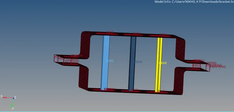
Mesh the Given component with the Size of 5 Units. Create 1D elements on the following component with given cross-section and DOF

a. Rod element:- Translational DOF should be Constrained with RBE2 link

Cross-Section: BOX- Dimension a= 12 mm

                              dimension b=10 mm

                              Thickness t= 0.75 mm

b. Beam element:- All DOF should be constrained with RBE3 link

Cross-Section: I Section- Dimension a= 8 mm

                                     Dimension b= 10 mm

                                     Dimension c= 8.5 mm

                                     Thickness t1= 0.75 mm

                                     Thickness t2= .6 mm

                                     Thickness t3= .6 mm

c. Bar element:-  Constrain only x and y DOFs With RBE3 link

Cross-section: X section- Dimension DIM1= 5 mm

                                             Thickness DIM2= 1.2 mm

                                             Dimension DIM3= 10 mm

                                             Thickness DIM4= 1.2mm

d. & e. Apply the mass of magnitude 10 with the RBE2 link

f. Join the two components with Spring elements

OBJECTIVE:
To mesh the given cad model and made as per the connections with proper dimensions assign the property of that elements and checck the dimensions related with object.mainly undestood by the rod,beam bar and springs connections for the bracket connections.Masses put into the object on RBE2 connections. 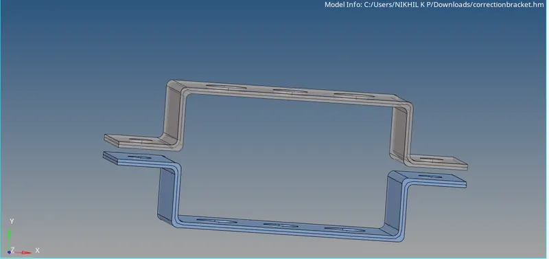
PROCEDURE:
*Download the file open the software check and import the model from IGES format ,after that delete the default component.

*MIDSURFACING: To make the mid surfacing for selecting the midsurface option on horizontal axis select auto midsurface option and select bracket one and assign the colour for that object.Then select next bracket2 midsurfacing is done and select colour.
Then slect the material on the rigth click and create option assign the material as per the two brackets with different properties are assigned and made the dimension of thickness measure with 'length tool' 5mm is measured length.

*MESHING: Meshing is done before that quick edits select the washer using a washer split and made the element.Now select 2D mesh automeshing and select bracket one and two meshing is done.
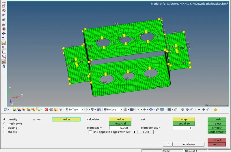
On meshing the element numbers are represented is like even numbers else correct the numers are even on mouse right or left click.
*RBE2 RBE3 connections made on the portions for rod,beam,bar element connections.now create the beam rod and bar elements property assign dimensions provide for the object on question.
*For that hyper beam or optistruct selected and create seperate property for the object for the three parts are created and make the property assign the parts also.Making the rods on the horizontal axis select rods CREATE/SELCT NODE1/SELECT NODE2/PROPERTY ROD/ELEMENT CROD and axis are selected.Now a rod is made on the portion.degree of freedom is 6 axises are selected for the rod element.
*For the same procedure for the beam and bar select BAR/SELECT NODES/CBAR/PROPERTY SLECET BAR/MADE ORIENTATIONS N1 N2 N3 /DEGREE OF FREEDOM/make the portions beam.
*Create a rbe2 connections on D na dE portions make connection between them and ID/MASSES/PUT MASS 10/SECLECT NODE /CMASS1 CREATE on both the sides.
*Finally make spring connection for the element select 1D/SPRINGS/SELECT NODE FOR FIRST BRACKET AND NEXT FOR SECOND ELEMENT/CREATE.
8All the connections are made to see the connections of bars and rods put an option is BOTTOM OF THE TOOL BAR 1D DETAILED ELEMENT REPRESENTATION COULD BE MADE VIEW THE OBJECT.
*Save the file.