Week 4-1D Element Creation Challenge
OBJECTIVE
To mesh the given component with the size of 5 Units, creating 1D elements on given component with given cross-section and DOF.
CAD MODEL IMAGE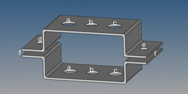
PROCEDURE
- Starting with selecting OptiStruct as default in user profiles
- Import the component using import geomentry in tool bar and file type as IGS
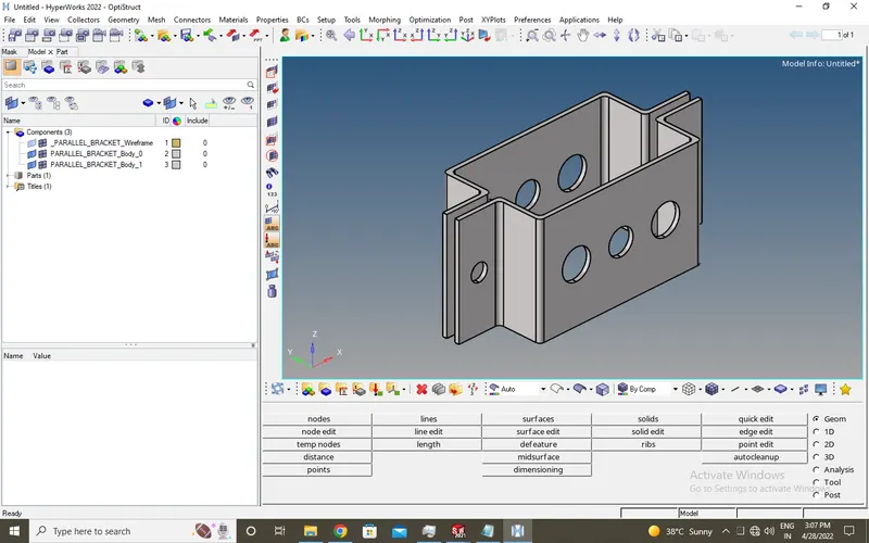
- First we convert the CAD Model to Surface
- Open midsurface in Geom, change extraction options to skin offset and extract the top geomectric surfaces and rename it as Bracket_1
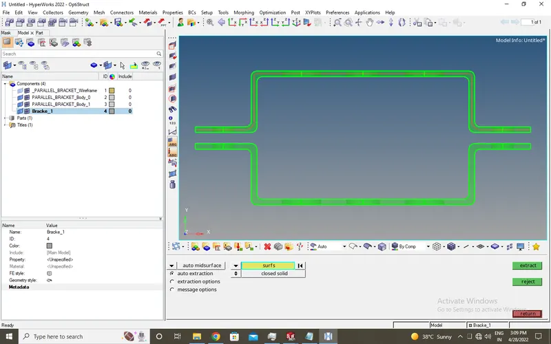
- Create a new component as Bracket_2 and do the above step for bottom geomectric surface.
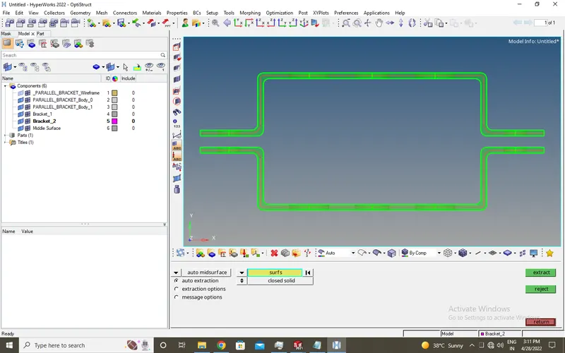
- Change the color of Bracket_1 and Bracket_2 as blue and green respectively
- Delete the diplayed surface using delete in tool bar and delete the components above Bracket_1 in tab area
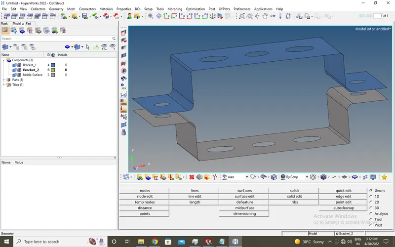
- After deleting open organize in tool at main menu bar, select bottom surface and move them (check whether model is in Bracket_2)
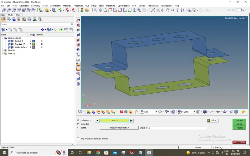
- Now delete the mid surface in components in tool area
- Thus CAD Model is converted into Surface
- Secondly, we mesh the given component
- Give washer split of offset value 8 at holes to surface component from quick edit in Geom
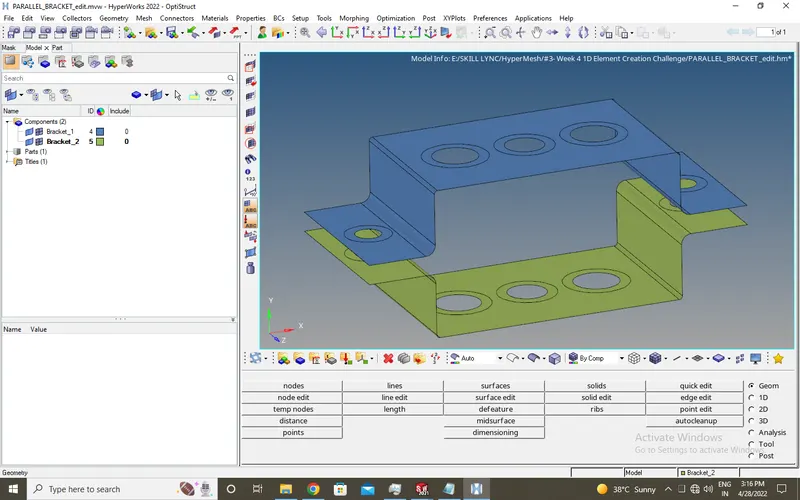
- Open automesh from 2D, by keeping element size to 5 with mesh type as mixed.
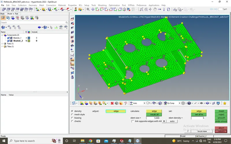
- Now adujust the nodes near holes for good and quality mesh, mainly near fillets.
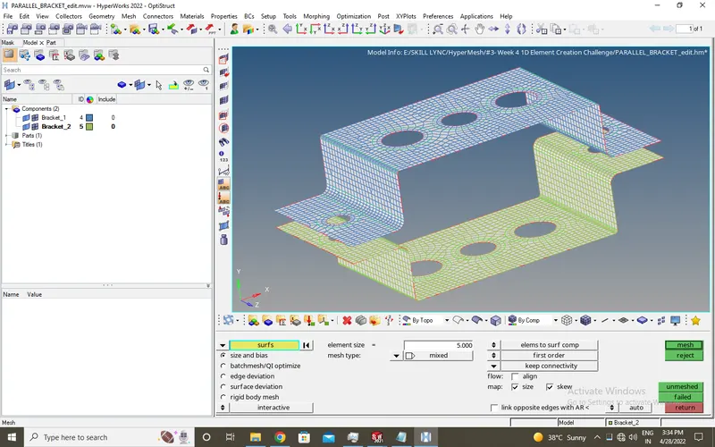
- Now Meshing of the component is compleated
- Thirdly, we will give RBE2, RBE3 at the holes and creating give cross-section
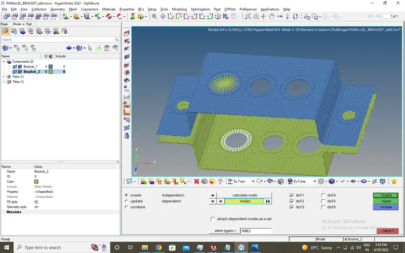
- a) Now open rigid in 1D, choose calculate nodes and multiple nodes and tick DOF1, DOF2, DOF3 only to constrain translation rotation.
- Place the nodes at 'a' hole and it's washer offset by changing to by path at blue surface.
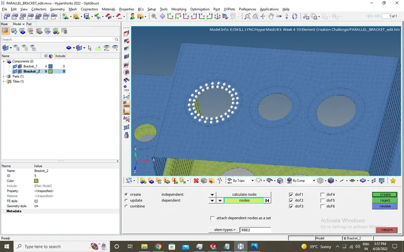
- Do the same step as above for green surface.
- b) Open RBE3 in 1D, choose calculate nodes and tick all DOF's for constraining.
- Place the nodes at 'b' hole and it's washer offset by changing to by path at blue surface
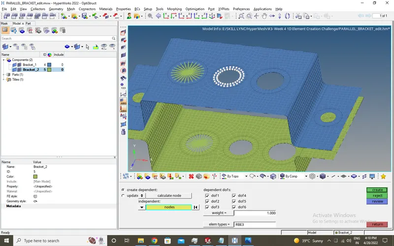
- Do the same step as above for green surface.
- c) Open RBE3 in 1D, choose calculate nodes and tick DOF1, DOF2, DOF4, DOF5 for X and Y constraining.
- Place the nodes at 'c' hole and it's washer offset by changing to by path at blue surface
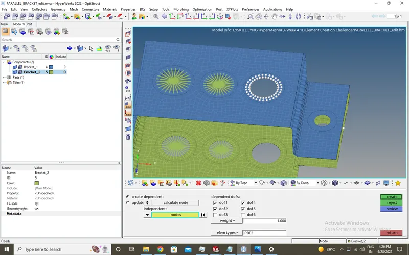
- Do the same step as above for green surface.
- Now for creating cross-sections, open HyperBeam, choose standard section
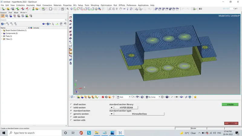
- click thinwalled box > create and rename as Rod for box cross-section
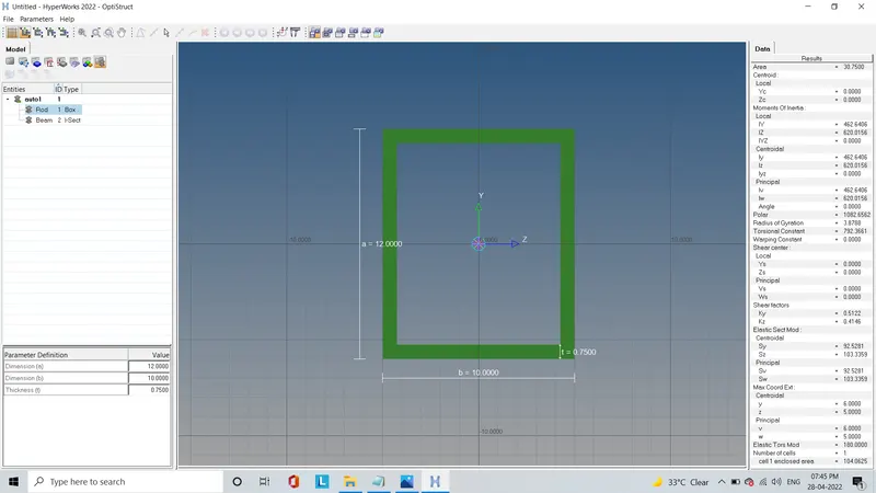
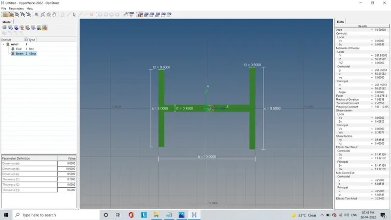
- click standard I section > create and rename as Beam for I cross-section
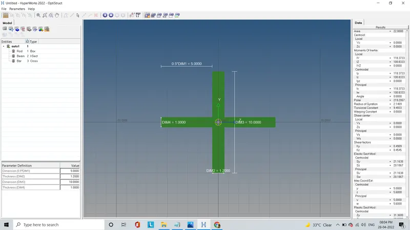
- click standard X section > create and rename as Bar for X cross-section
- Thus RBE2, RBE3 and cross-sections are created as required
- Finally, we'll create rod, beam, bar and assign them cross-sections at 'a,b,c' and mass at 'd,e' and spring elements at 'f'
- To create a rod, click rod in 1D and select top and bottom nodes of RBE2 and change elem type to CROD

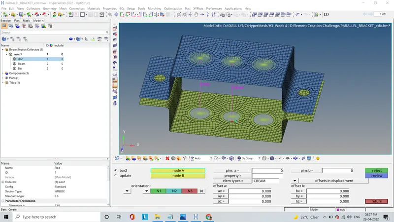
- To create a beam, click bars in 1D and select top and bottom nodes of RBE3 and change elem type to CBEAM
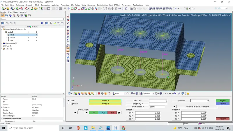
- To create a bar, click bars in 1D and select top and bottom nodes of RBE3 and change elem type to CBAR
- Now for assigning cross-sections, first create properties as rod, beam, bar
- Then choose PROD as Card Image and Rod as beam section for Rod
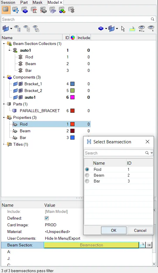
- And then choose PBEAM and PBAR as Card Image and Beam and Bar as beam section for Beam and Rod
- Now to update these properties to model open Rod and update property as Rod and update it

- Then do the same for upadeting Beam and Bar but open bars instead of rod
- Now change to 1D Detailed Element Representation
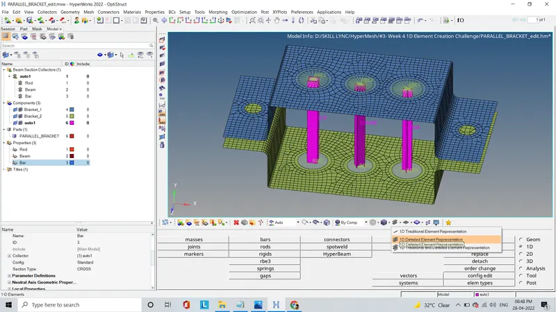
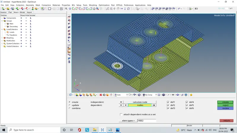
- For Creating mass create RBE2 using rigid in 1D at 'd,e'
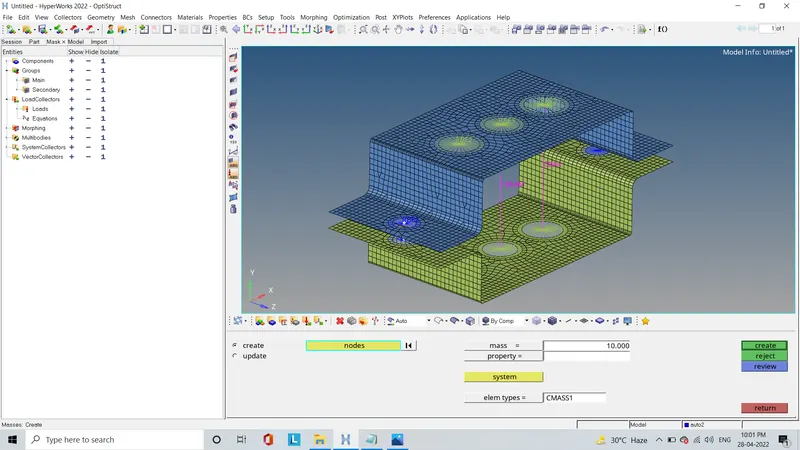
- Open masses in 1D, create masses with magnitute 10 and by change elem types to CMASS1
- For creating Spring element, open connectors > spot, change type to spring and select nodes at 'f' and two components by change tolerance to 15 and click create.
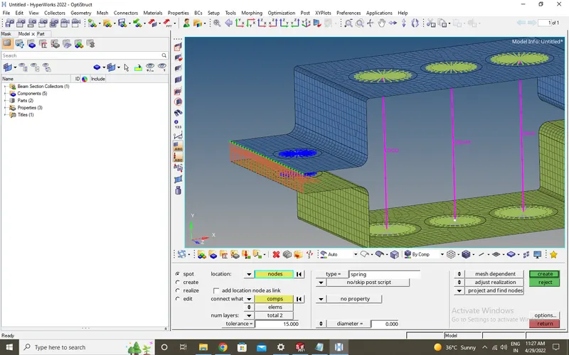
- Thus rod, beam, bar are created and assigned them cross-sections at 'a,b,c' and mass at 'd,e' and spring elements at 'f'
RESULTS
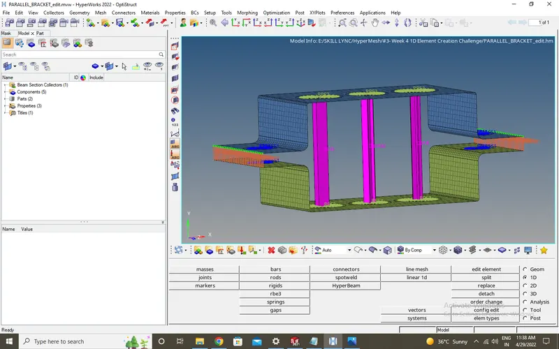
Thus the given component is meshed with the size of 5 Units, created 1D elements on given component with given cross-section and DOF's.
FINAL MODEL IMAGE