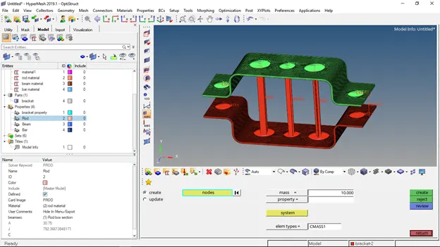
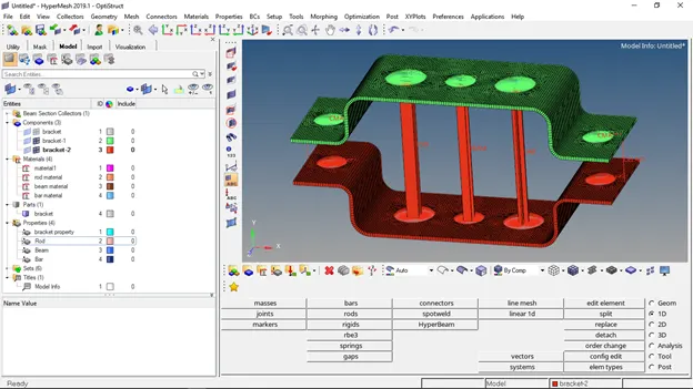
Week 4-1D Element Creation Challenge
WEEK-4 Challenge: 1D element creation
To begin with 1D element creation at first, I created a 3D model of the bracket in solid works with the dimensions shown in the figures
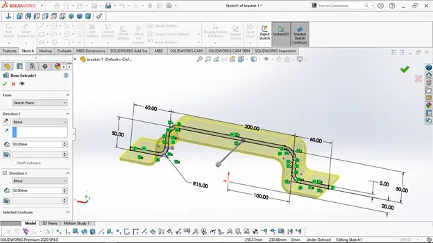
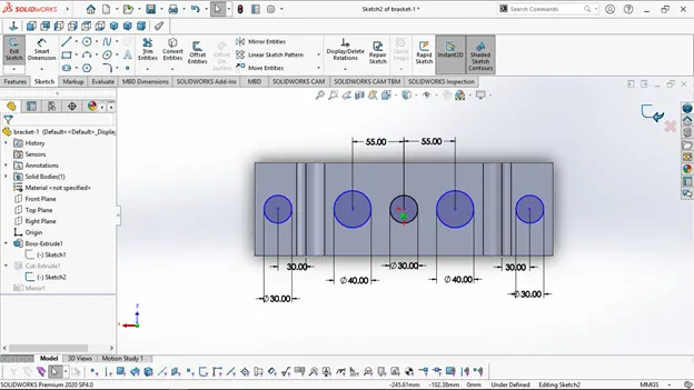
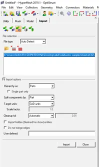
And then Importing the file into Hyper mesh workspace.
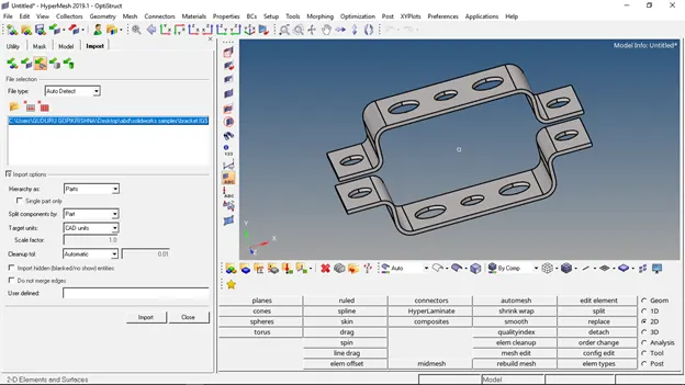
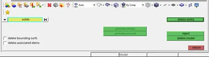
Now all the solids in the bracket are deleted  as they are not required, hence we are left only with the surfaces
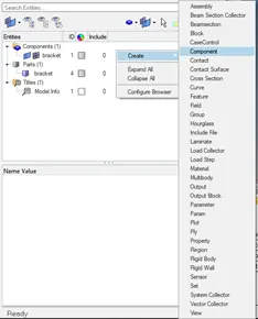
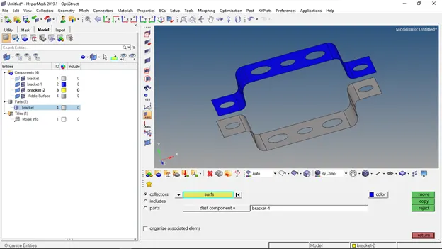
Now time to create a mid-surface for the brackets, before we create the mid-surface it is ideal to create a new component and rename it as bracket-1 and bracket-2 as is shown in the figure.
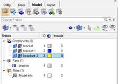
Now it’s time to create the mid-surface  for the brackets
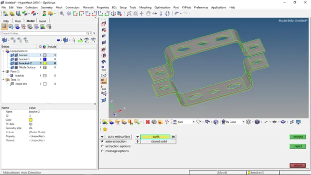
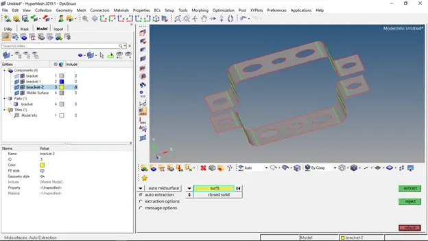
And when we extracted the mid-surfaces, we don’t need the original surface anymore so we can delete it or hide it, and time to move them to the components we created earlier, and this is done in the tool’s menu --> Organize
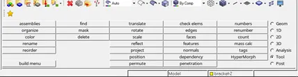
Select the top surface, surfs --> select by attached --> to dest component --> bracket-1
Repeat same for the other surface to bracket-2
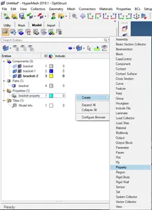
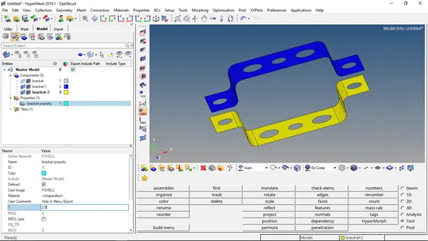
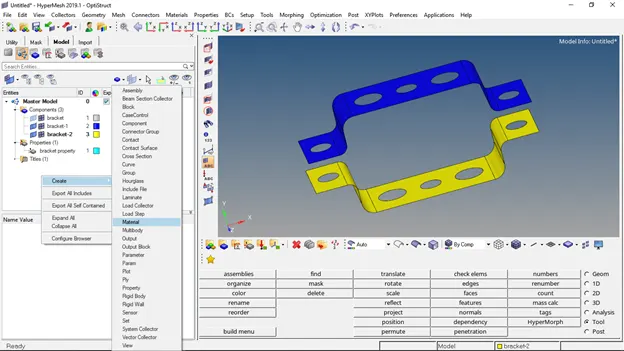
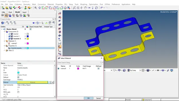
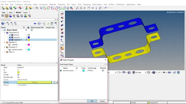
Now, when we have to create the properties for the bracket-1 and bracket-2 and also add material to the brackets we need to select card image as PSHELL and T thickness is also to be specified
Now, before meshing it is ideal to do the auto cleanup, so I have added washer splits near the holes
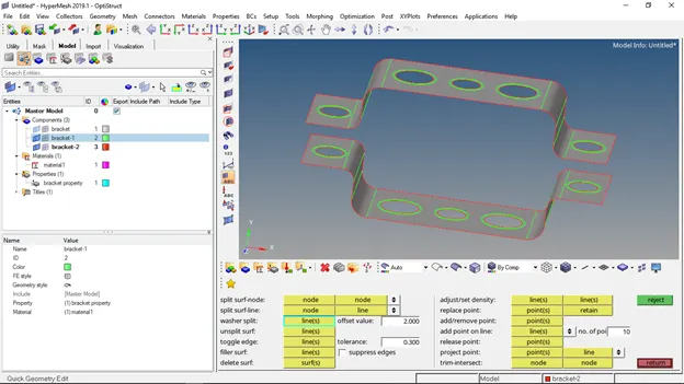
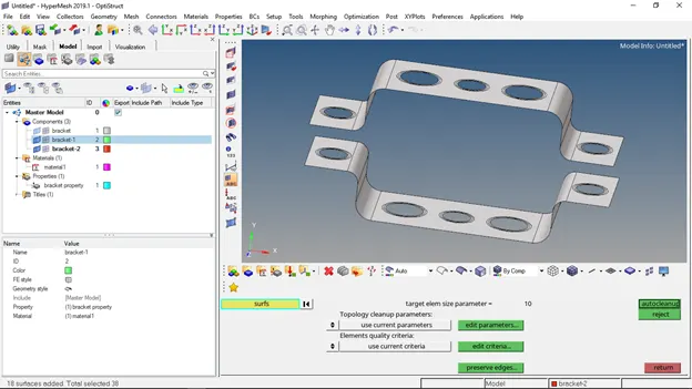
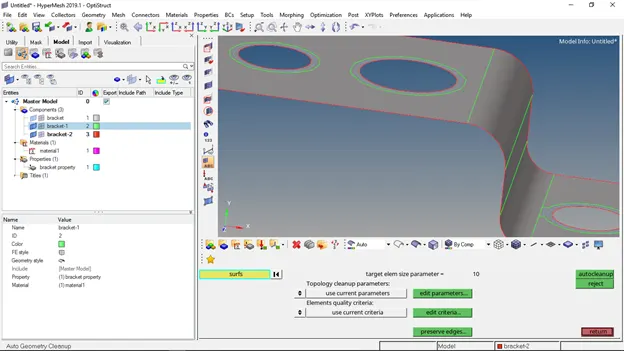
As the auto cleanup, sometimes doesn’t work as we wanted as you can see in the above image, I am doing it manually and now we can go for the 2D meshing of the surface
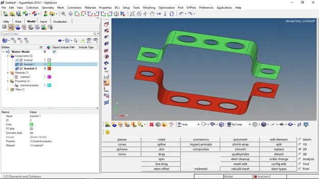
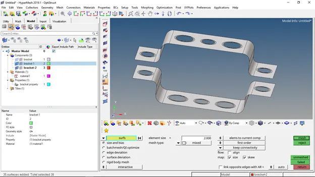
2D --> Auto mesh, select the surfaces, and mesh the components
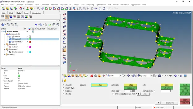
And by changing the number of nodes at the holes I have recalculated and meshed
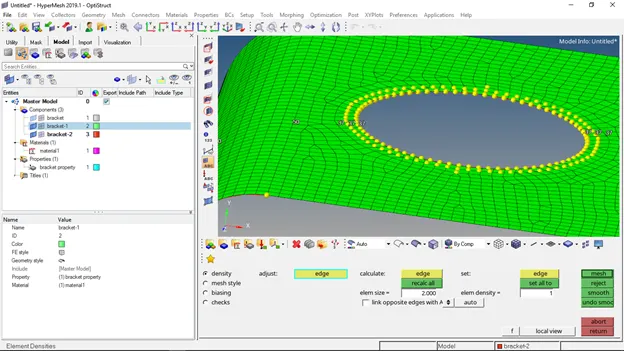
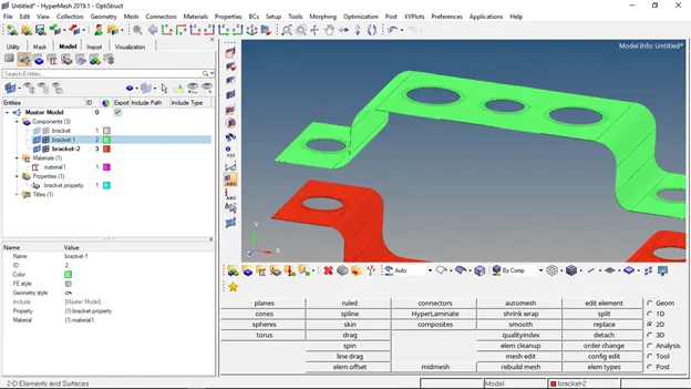
Now the meshing is done we don’t need the surface so, hiding the surfaces
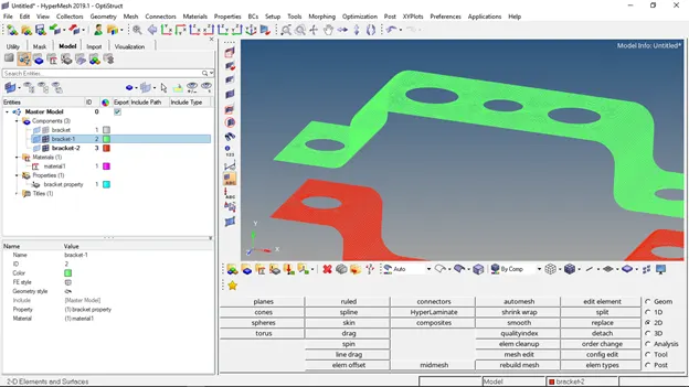
Now the only visible is mesh
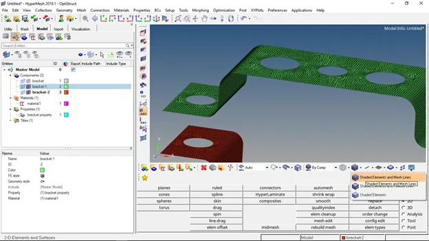
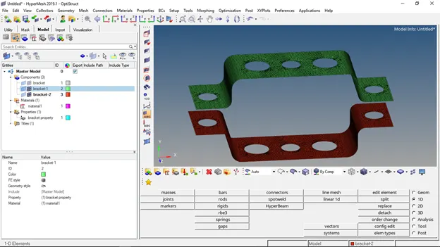
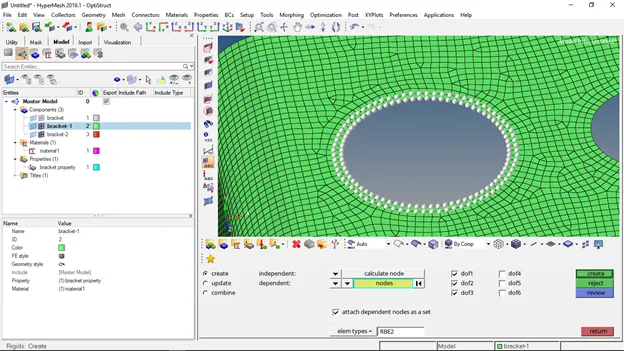
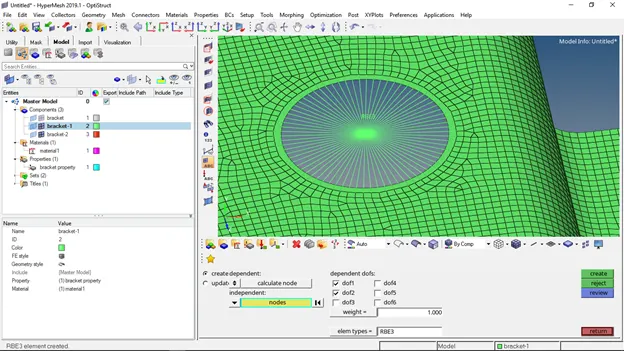
Now can create RBE2 and RBE3 elements at the holes
- Translational DOF is Constrained with RBE2 link
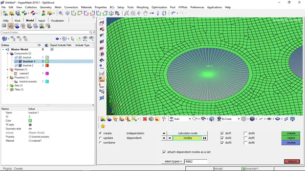
- All DOF is constrained with RBE3 link
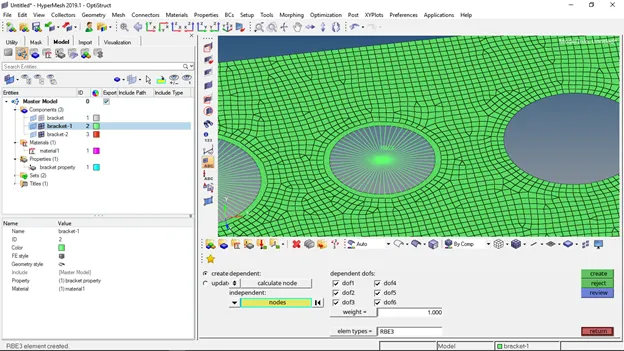
- Constrained only xand y DOFs With RBE3 link
mass of magnitude 10 with the RBE2 link is applied at d. and e.
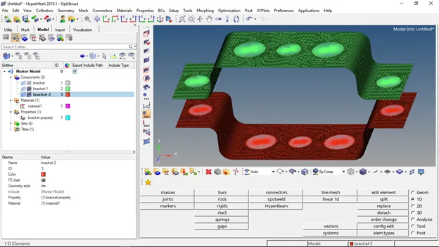
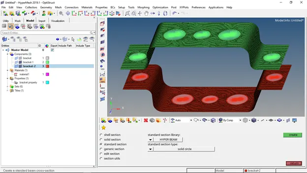
Before creating links, first, create the cross-sections and name the links as given, go to 2D --> Hyper beams --> standard section --> box --> created
Cross-Section: BOX- Dimension a= 12 mm
dimension b=10 mm
Thickness t= 0.75 mm
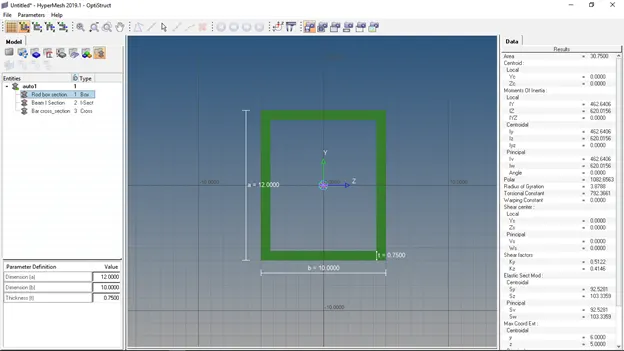
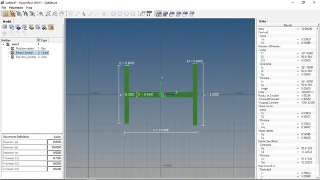
Cross-Section: I Section- Dimension a= 8 mm
Dimension b= 10 mm
Dimension c= 8.5 mm
Thickness t1= 0.75 mm
Thickness t2= .6 mm
Thickness t3= .6 mm
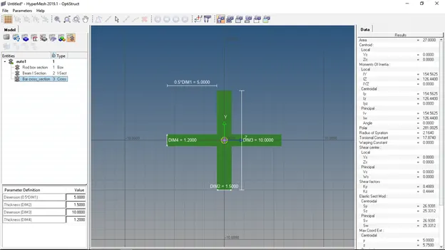
Cross-section: X section- Dimension DIM1= 5 mm
Thickness DIM2= 1.2 mm
Dimension DIM3= 10 mm
Thickness DIM4= 1.2mm
Now create the links by selecting the nodes of both ends for bar, Rod, and Beam
Rod --> Select the two RBE3 elements and select the element type as CRod and also select the cross-section as Rod
Beam --> Select the two RBE2 elements and Select the element type as CBeam give the cross-section plane N1, N2 and also select the cross-section as Beam
Bar --> similar to Beam select element type as CBar give the cross-section plane N1, N2 and also select the cross-section as a bar
Mass --> select the two RBE2 elements and give magnitude as 10 and we can also add material to it
Spring Element --> select two nodes at the edges on the brackets and it crates, Changes the element to CELAS1
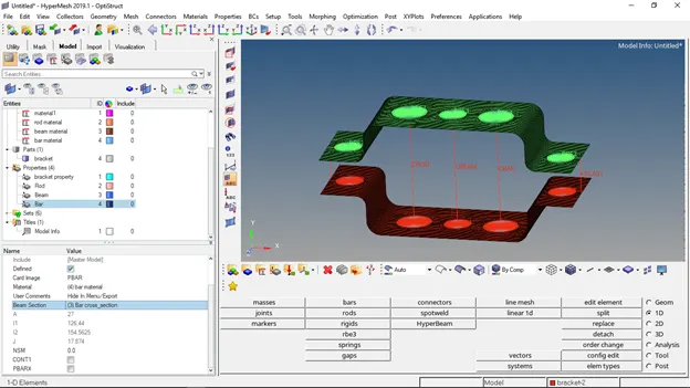
And now create the properties and materials for the links as Rod, Beam, bar and update the properties for the links,
To view the cross-section 1D detailed element representations
To view 2D to 3D go to 2D detailed element representation