Week 4-1D Element Creation Challenge
1D Element Creation
Objective: The main objective of this project is to extract the mid surface to the model and create 1D element to the given model.
PROCEDURE:
- Import the model.
- Extract the mid surface.
- Assign the property.
- Create the 1D element.
IMPORT THE MODEL:
- To import the model to Hyper mesh, we need to go to import option and select the required path from the system and import the model/geometry to the work window.
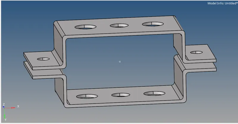
EXTRACT MIDSURFACE:
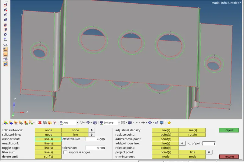
- To extract the midsurface, go to Geometry-midsurface and extract it while extracting select the option offset+planes in extraction options, so that the fillet regions will extract correctly.
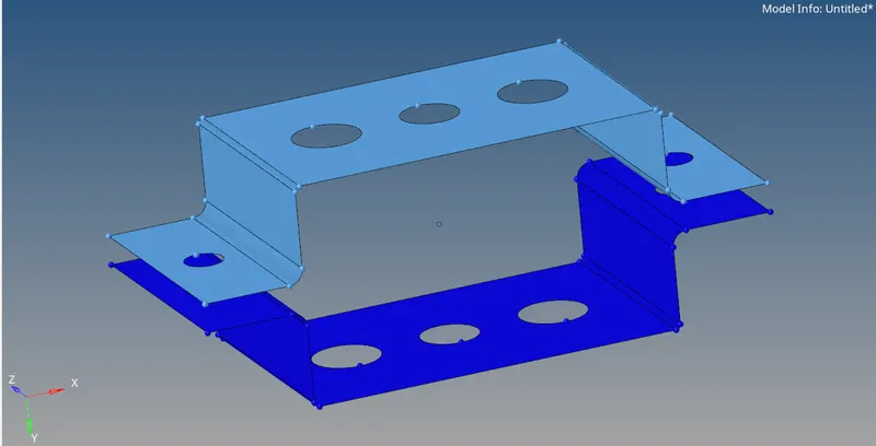
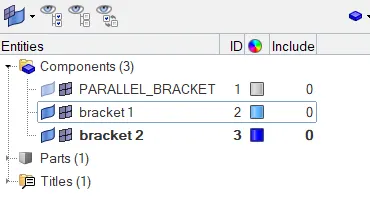
- Since we need the separate midsurface bracket for the model. Create the component in the tree and duplicate the surface.
- Go to tool-organise select the surface and press move. So that we will have two different surfaces for two brackets.
ASSIGN THE PROPERTY:
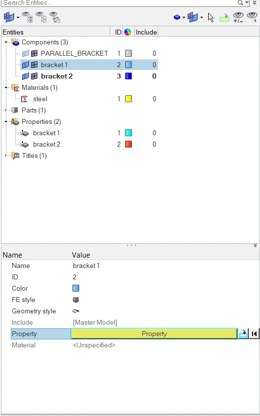
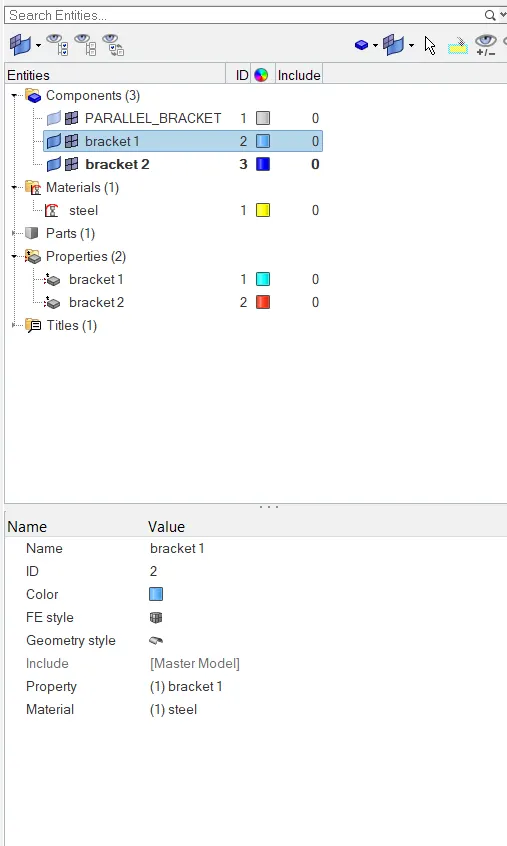
- To assign the property , go to tree and select create-property.
- Create two different properties for the two brackets.
- Assign the thickness and material by measuring the thickness of the model, since the model is having same thickness assign the same thickness to the both properties.
CREATE 1D ELEMENT:
As per challenge the 1D elements are RIGID or RBE2 elements and RBE3 elements.
Difference: Both elements "look" the same, in that they have a single node connected to one or (usually) multiple other nodes. The difference is that the RBE2 element adds (infinite) stiffness to the structure, while RBE3 elements "distribute forces" around the connected nodes, without adding any stiffness.
FOR a-a: We need to create the RBE2link with translational DOF
- To create the RBE2 link go to 1D- rigid. Rigid element is also called as RBE2 element.
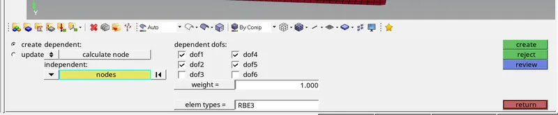
- Select the nodes or calculate the nodes by path and select the DOF from the table. As mentioned only translation DOF should be constrained to the a-a hole. In the table DOF1,DOF2,DOF3 refers to Translational DOF in X,Y,Z and DOF4,DOF5,DOF6 is rotational DOF in X,Y,Z directions.
- Select the DOF as mentioned and create.

ROD ELEMENT:
- To create the rod element go to 1D rods. Create the rod element; make sure we have selected the CROD in the element type.

CREATE BOX/I /X SECTION:
- To create the sections we need to go to 1D- Hyper Beam. Go to standard section, in standard section library select the Optistruct. In standard section type select the required section. For a-a hole it is BOX cross section. For b it is I section. For C it is X section.
- Apply the dimensions as mentioned and return to the hyper mesh.
FOR B: All DOF should be constrained with RBE3 link.
- To create the RBE3 link, go to 1D- RBE3 element.
- Create the RBE3 element by selecting the nodes by path and create.
- Apply all DOF as mentioned in the challenge.
NOTE: For c,d,e the same procedure is followed by selecting the below mentiond process.
BEAM AND BAR ELEMENT:
- To create the BEAM/BAR element, go to 1D rods. Create the bar element, select the two nodes where to create the element and select the direction by N1 and N2 nodes, make sure we have selected the CBEAM/BAR in the element type.

PROPERTIES FOR SECTIONS:
- Create the property for the sections individually, because we can give different material and card image.
- Give the card image correctly for the sections.
- For ROD the card image is PROD, for Beam it is PBEAM, for Bar it is PBAR.
- Select the beam section in the same property and apply for the elements.
APPLYING MASS:
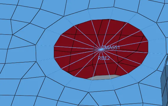
- To apply mass go to 1D-masses and create the mass by selecting the node and apply mass of 10. In element type select CMASS1.

APPLYING SPRING ELEMNETS:
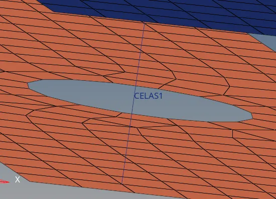
- To apply spring element, go to 1D-springs create the spring element by selecting the two opposite nodes. The DOF can be in any direction. For spring element the element type is CELAS1.

NOTE: To view all the applied parameters in the model and to view the assigned thickness turn on 2D detailed Element Representation. To view the properties assigned select BY PROPERTY below the graphical window.
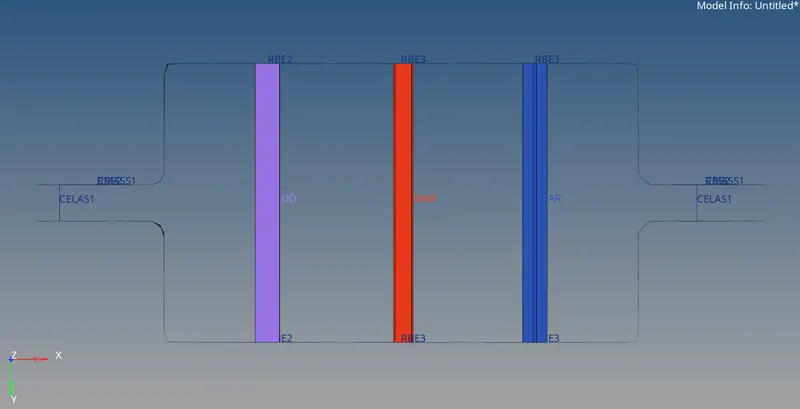
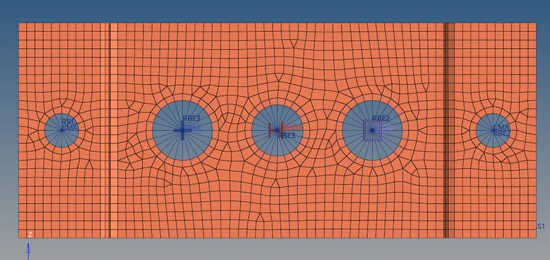
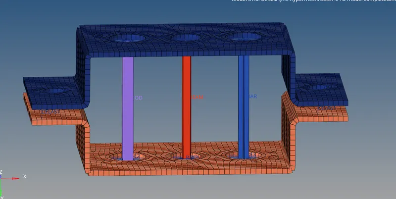
CONCLUSION: From this challenge we have created the 1D elements to the model. The final outputs of the model are shown below.