Week 4-1D Element Creation Challenge
OBJECTIVE: Mesh the Given component with the Size of 5 Units. Create 1D elements on the following component with given cross-section and DOF.
- Rod element:- Translational DOF should be Constrained with RBE2 link
Cross-Section: BOX- Dimension a= 12 mm
dimension b=10 mm
Thickness t= 0.75 mm
- Beam element:- All DOF should be constrained with RBE3 link
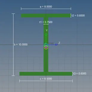
Cross-Section: I Section- Dimension a= 8 mm
Dimension b= 10 mm
Dimension c= 8.5 mm
Thickness t1= 0.75 mm
Thickness t2= .6 mm
Thickness t3= .6 mm
- Bar element:- Constrain only xand y DOFs With RBE3 link
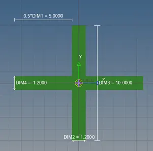
Cross-section: X section- Dimension DIM1= 5 mm
Thickness DIM2= 1.2 mm
Dimension DIM3= 10 mm
Thickness DIM4= 1.2mm
- & e. Apply the massof magnitude 10 with the RBE2 link
- Join the two components with Spring elements.
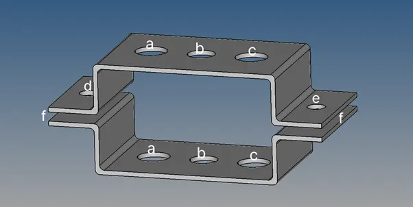
PROCEDURE:
STEP 1: Creating Mid surface and Meshing
In Geometry select midsurface and select autoextract, then select the surface for midsurfacing. Assign a name for the obtained midsurface and repeat the process for the next surface. Here the bracket 1 is assigned with colour red and bracket 2 is assigned with colour green.
The obtained midsurface is auto meshed with element size 5 units.
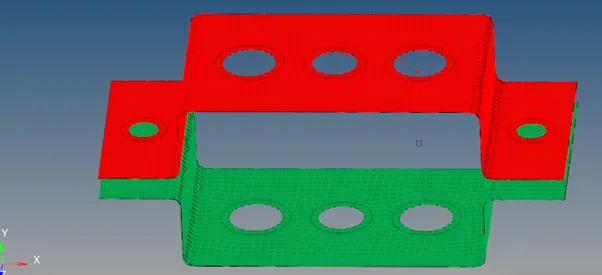
STEP 2: Creating 1-D elements
Rod element: Here the link chosen is rigid (ie) RBE2 from geometry. Here the nodes are created along the path where the rod element is created. The dof of 1-3 are selected since the translational degree of freedoms are constrained. Thus the rod element is created.
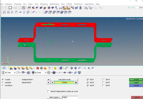
In order to create the cross section the Hyperbeam tool is used from 1D and the various required cross section of beam, bar and rod are created.
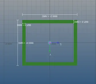
Similary in 1D option we create the beam by selecting bar option and in bar we choose the element type as CBEAM . The remaining steps are same as created above. Here the properties of these beam rod and bar are being assigned by creating new properties. Here all the dof are constrained.
In order to include the properties the update option is used and assign the properties of the respective 1d element.
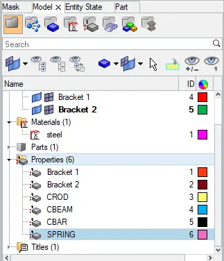
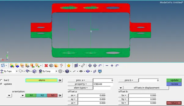
Similarly as beam the bar element is created by assigning the properties of bar and constraining the degree of freedom in x and y direction (ie) by selecting dof1 and dof2 and unselecting the remaining.
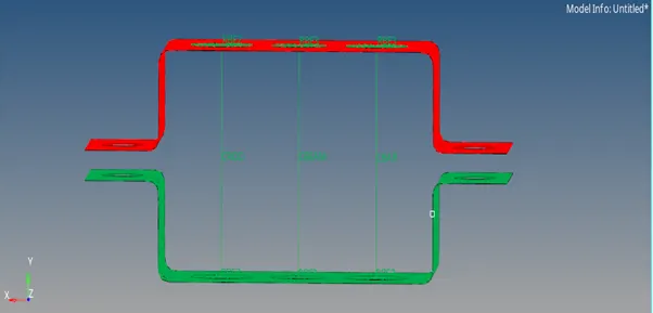
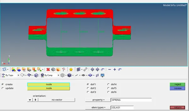
In 1D select masses and select the node where the mass is to be assigned. Thus, the required mass of 10 units is assigned to the respective sections (d & e). Here the spring element is attached using the spring tool. For assigning the property create a new property spring and select HM_ELAS in card images. Thus the spring element is created.
In order to view the element in 2d select 1D detailed element representation from menu bar and to view the brackets in 2d select 2D detailed element representation from menu bar.
Thus the required 2D representation is obtained.
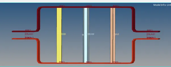
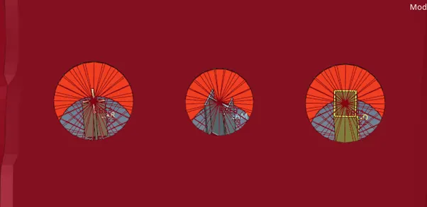
RESULT : Thus the given component is meshed and the respective 1D element with assigned cross section have been created.