Week - 4
CONTROL LOGIC BY MATLAB
AIM:The aim is to implement control logic of a “washing machine” using Stateflow.
OBJECTIVE:
If the power supply is available, the system gets activated
- If the Water supply is not available, stop the process & indicate through LED
- Soaking time should be 200s followed by Washing time of 100s.
- Then rinsing happens for next 20s & dryer runs for 50s
MODEL OF WASHING MACHINE:
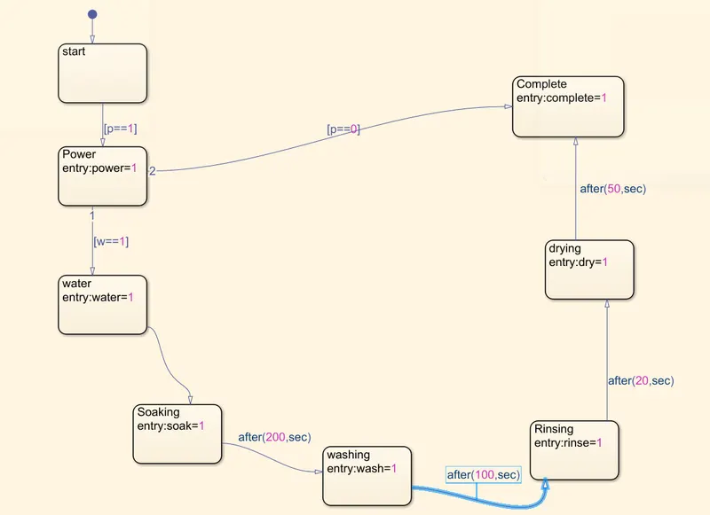
- This is done in Simulink by using chart.
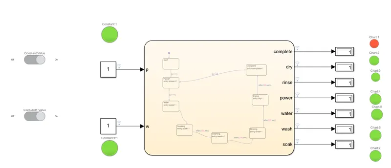
- As per given conditions our washing machine model is prepared as seen in above picture.
- Washing machine will have five stages like watering,soaking,washing,rinsing,drying.
- At the begining when the power is on watering will takes place and the process continues in the given time.
- In our model when p==1 the power is on, when p==0 power is off.
- In same manner w==1 watering is on,when w==0 watering is off.
- As per given condition soaking is done for 200 sec, so from soaking to washing time is taken as after 200 sec.This is written as after(200,sec) in matlab syntax.
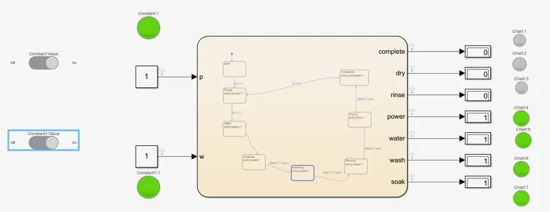
- Washing time is 100 sec.So the time between washing and rinsing is taken as 100sec.
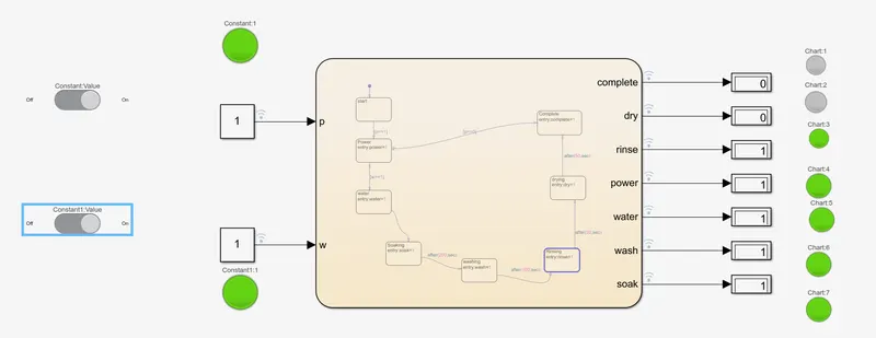
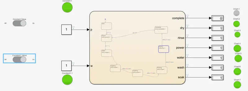
- In the same manner rinsing and drying is taken.
- We need to give input and output data for the state to run.
- The input and output data are given.
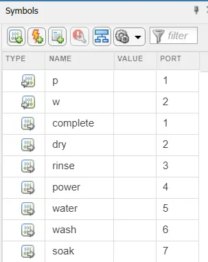
here input datas are the value of p and w.The output datas are remaining data.
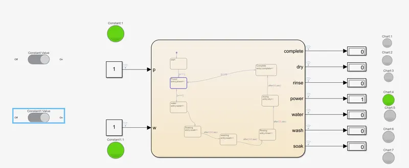
- A constant blocks are given as input data and output data is displayed in the display block.
- The constant is taken as one in all the cases.
- When constant value one is given as input data which is power,then the circuit runs and gives the output power value as 1.
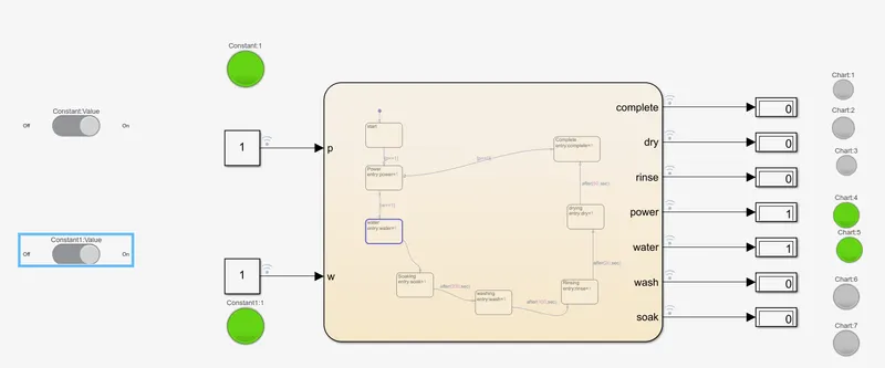
- Same pattern follws for every case.
- Lamps are connected to the output data,i.e if the value display one then the lamp is turned on.
- After all the process is completed the led light turns on in RED colour.
WHEN POWER IS ON AND WATER IS ON:
WHEN POWER IS ON AND WATER IS ON(Started filling):
WHEN SOAKING PROCESS TAKES PLACE:
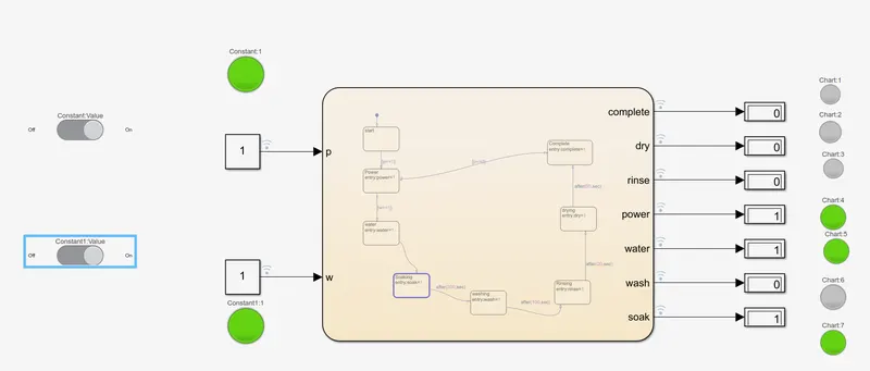
WHEN WASHING PROCESS TAKES PLACE:
WHEN RINSING PROCESS TAKES PLACE:
WHEN DRYING PROCESS TAKES PLACE:
WHEN ENTIRE PROCESS IS COMPLETED:
GEAR SHIFT IN SIMULINK:
OBJECTIVE:
Speed Range(kmph) Gear
0 to 15 1
16 to 25 2
26 to 40 3
41 to 60 4
Above 61 5
- We need to create a gear shift logic in simulink.
- When the speed is 0-15 the gear should be 1
- When the speed is 16-25 the gear should be 2
- When the speed is 26-40 the gear should be 3
- When the speed is 41-60 the gear should be 4
- When the speed is above 61 the gear should be 5
LOGIC:
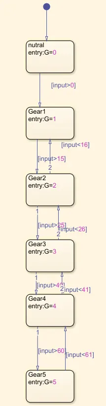
- The logic behind this chart is,when the input is greate than 0 the gear changes to 1 from nutral position.
- When the input is greater than 0 the gear changes to 1.
- When the input is greater than 15 the gear changes to 2.When the input is between 0-15 the gear is 1.
- When the input is greater than 25 the gear changes to 3.When the input is between 15-25 the gear is 2.
- When the input is greater than 40 the gear changes to 4.When the input is between 25-40 the gear is 3.
- When the input is greater than 60 the gear changes to 5.When the input is between 40-60 the gear is 4.
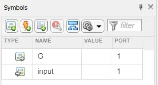
- The input value is taken as input and G value is taken as output.
- Input is a constant of any value.Output is G value i.e gear value maximum value is 5.
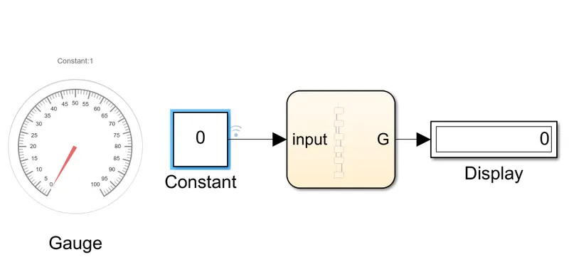
- A gauge is connected to this to show the reading.
- Above image is in nutral position.
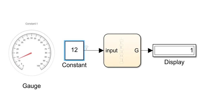
When the speed is <15 the gear is 1. The gauge indicates the speed.
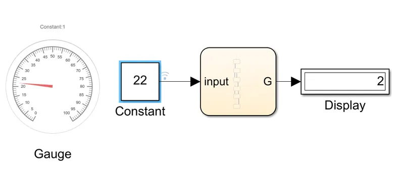
When the speed is <25 the gear is 2. The gauge indicates the speed.
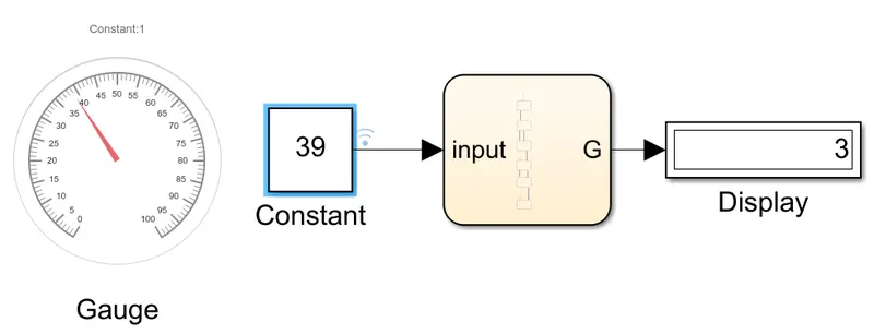
When the speed is <40 the gear is 3. The gauge indicates the speed.
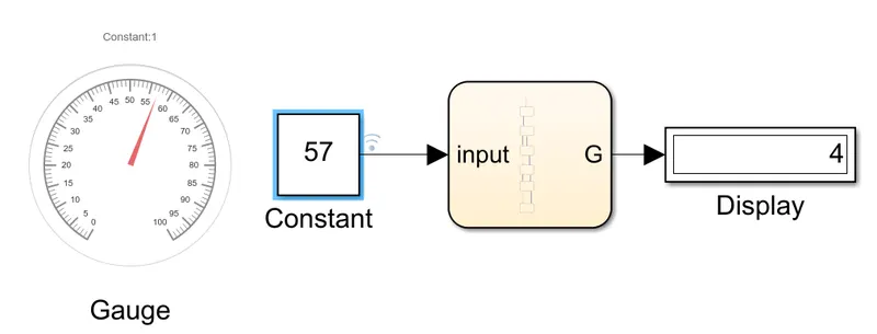
When the speed is <60 the gear is 4. The gauge indicates the speed.
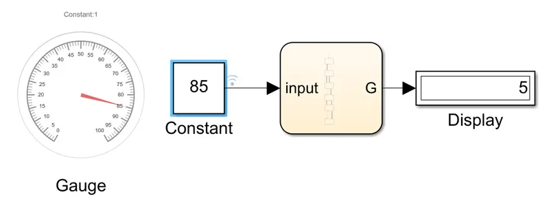
When the speed is >60 the gear is 1. The gauge indicates the speed.
CONCLUSION:
Therefore the logic for the washing machine model and Gear shifting model is done and the output is shown in the display and the gauge respectively.