Implementation of State Flow Control Logic of Washing Machine and Gear Transmission
Objective 1: To implement control logic of a “washing machine” using Stateflow as per given sequence:
- If the power supply is available, the system gets activated
- If the Water supply is not available, stop the process & indicate through LED
- Soaking time should be 200s followed by Washing time of 100s.
- Then rinsing happens for next 20s & dryer runs for 50s
- After all the processes have completed turn on the finished LED
Methodology:
Implementation of control logic using State Flow:
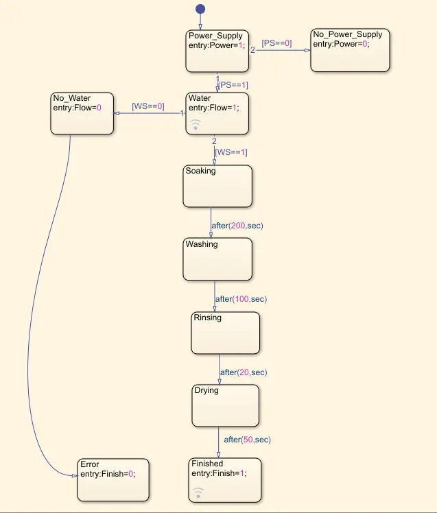
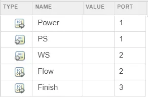
PS,WS - Input Data, where PS denotes Power Supply and WS denotes Water Supply
Power, Flow and Finish - Output Data
Simulink Model with State Flow chart:
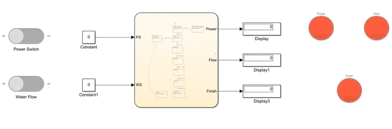
Explanation of the model:
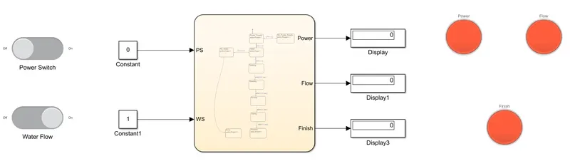
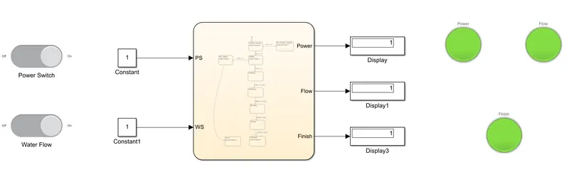
Here, as we can see two slider switches and 3 lamps are provided and connected with specific model parameters.
One switch is connected to the constant block linked with the input data PS which is responsible to turn ON (1) and OFF (0) the electric supply. Another one is connected with the constant linked with WS which is responsible for water flow.
Lamps displays two colours, Red indicates 'OFF condition' in the case of Power, 'No water flow' in the case of Flow and 'Process Incomplete' in the case of Finish lamp. Green indicates 'ON condition', 'Water Flow' and 'Process Complete' in the case of Power, Flow and Finsh lamps respectively.
Results:
1. When Power supply is ON and Water supply is OFF
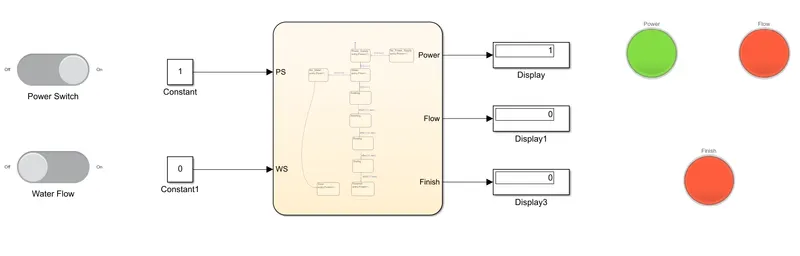
2. When Power Supply is OFF and Water supply is ON
3. When Power Supply and Water Supply is ON
Objective 2: To make a Simulink chart for the “Gear shift” logic as per below conditions:
Speed Range(kmph) Gear
0 to 15 1
16 to 25 2
26 to 40 3
41 to 60 4
Above 61 5
Methodology:
Implemetation of control logic using state flow:
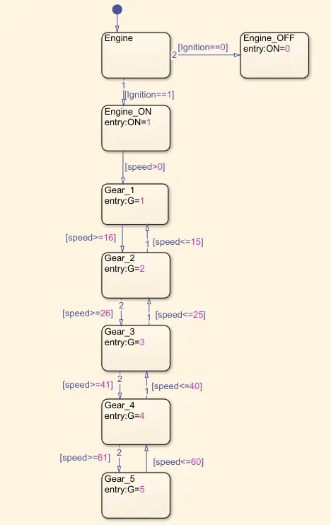
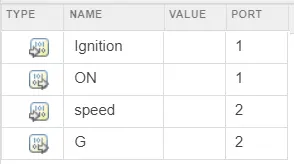
Ignition and Speed are input data.
ON and G are output data where ON represents engine ON/OFF condition and G represent the Gear in which the vehicle is moving.
Simulink Model:
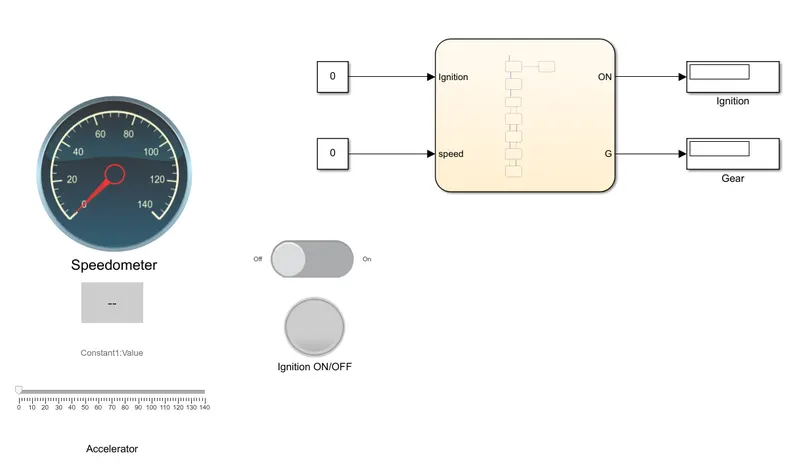
Explanation of the model:
The state flow chart is connected with the simulink model. It consists of a speedometer and slider linked with input speed and a dashboard display linked with G which shows the gear number corresponding to the speed. It also have a slider switch used to ON and OFF the engine connected to Ignition and a lamp connected to the ON output data which will be Red during Engine OFF condition and Green during Engine ON condition
Results:
1. When Engine is OFF
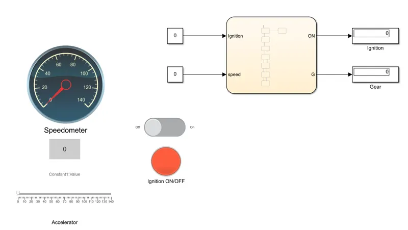
2. When speed ranges from 0-15kmph - Gear 1
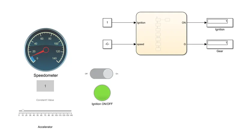
3. When speed ranges from 16-25kmph - Gear 2
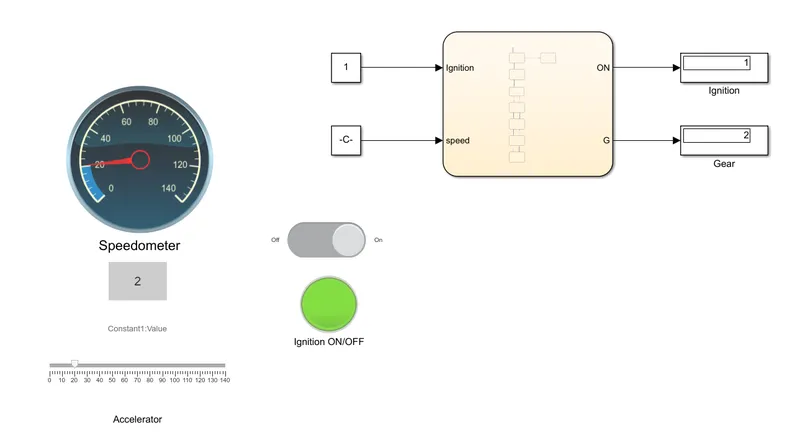
4. When speed ranges from 26-40 kmph - Gear 3
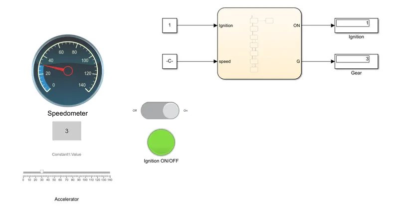
5. When speed ranges from 41 to 60 - Gear 4
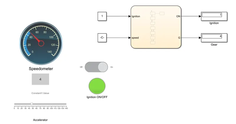
6. When speed ranges above 61 - Gear 5
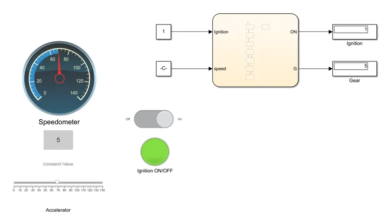
Links:
Gear Transmision: https://drive.google.com/file/d/1K9EdJH1WosQzyQolS9c463ECnFfpiJAj/view?usp=sharing
Washing Machine: https://drive.google.com/file/d/1lLQiJOd_mLeFfXm5xaQ1JZnZRafSqRyx/view?usp=sharing