PREPROCESSING ON A BOTTLE CAP COMPONENT BY USING ANSA
AIM :
To Performing the preprocessing operation on a given Bottle Cap component.
OBJECTIVES :
1) Checking the entire given geometry and cleanup the geometrical Error if required.
2) Extracting the appropriate middle surface from the parent component.
3) Set the Quality Parameter and Mesh Element Parameters.
4) Perform Meshing Operation on a mid surface.
5) Set the Property card to the surface and providing the appropriate thickness.
CAD MODEL IMAGE :
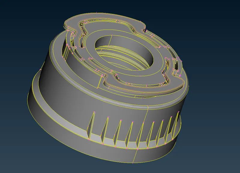
Open the ANSA software, import the appropriate file which is Bottle Cap by using open graphical user interface option. Once open the bottle model, it will looks like as shown in the below image.
As We observe the model, it has symmetry in shape about the Y axis except few places. If, we have to work on half a portion and then we easily able to rotating it about an Y axis by using rotate option.
After Open the bottle cap model, it will showing from the graphical window like as shown in below image.
PROCEDURE FOR ATTAINING THE OBJECTIVES :
I) Checking the Geometry :
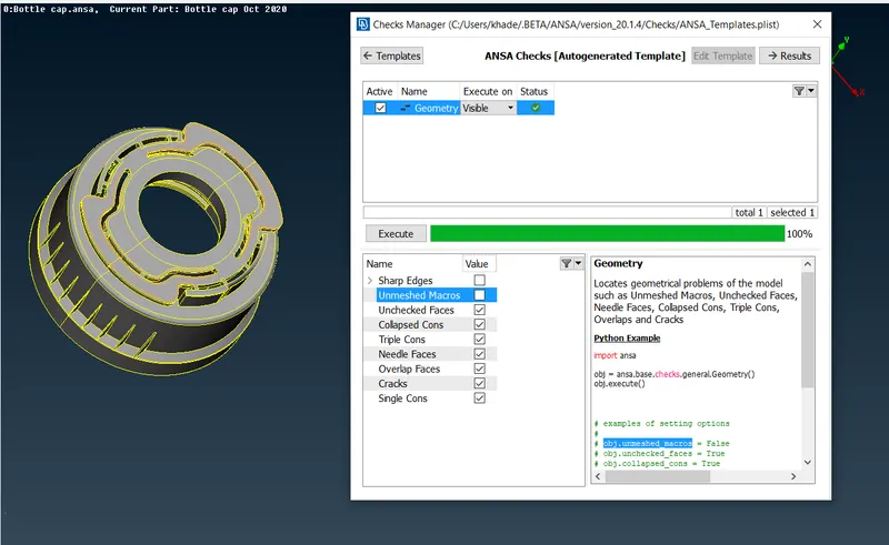
Before going to meshing on a component, we have to checking the entire parent geometry if there's any geometrical issues are presented or not. Inorder to checking the model, make sure we have to select the parameters which are gonna concerned in this model.
ANSA have default template which have some few important parameters are available, we have select all those things except "Sharped Edges" and "Unmeshed Macros". Because, those are no need for this case.
After complete the parameters selection, make sure keep "Visible On" from the "Execute On" option and then click the Execute option to which finding the errors from the visible geometry.
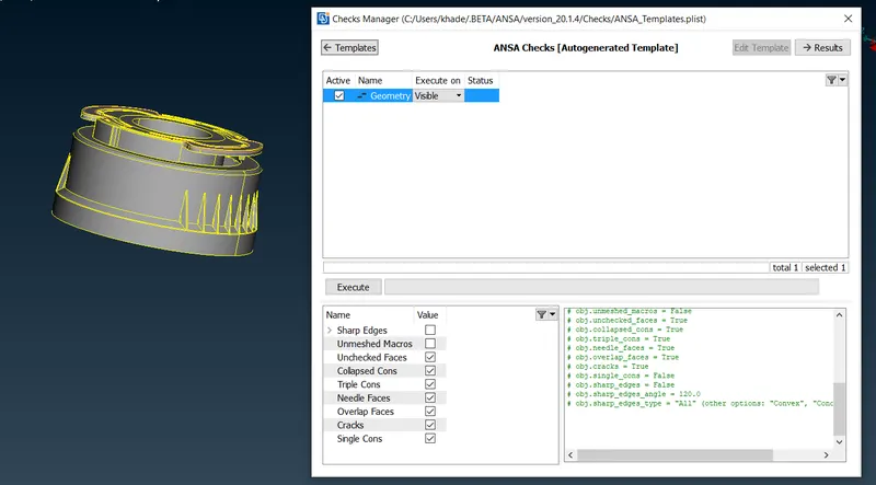
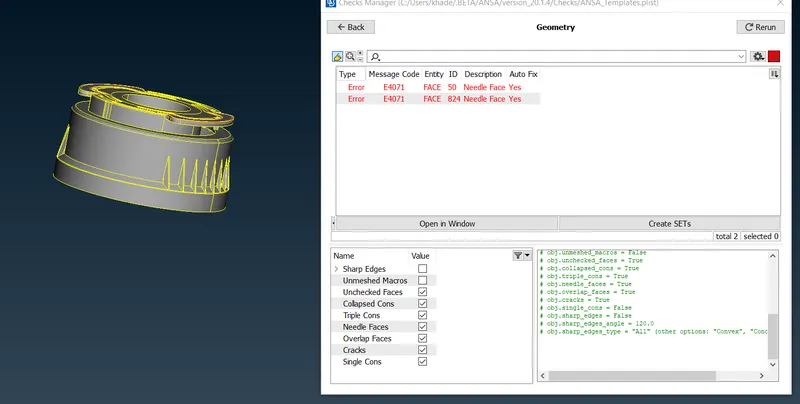
After Execution, it will automatically finding the issue from the model. If any errors were presented in the visible model, immediately it has shownup in the same window What error and Where it is.
This component have few errors on it. Which is for "Needle face" as shown up in the below image.
After Showing the errors, Select any one of the error from which is presented on a tab, followingly right click on it. We have one option called "Show Only" which means it will showing exact error place from our component.
After click the show on option, it will showing only exact error location from the entire visible geometry and remaining things are hide. As shown in the below image.
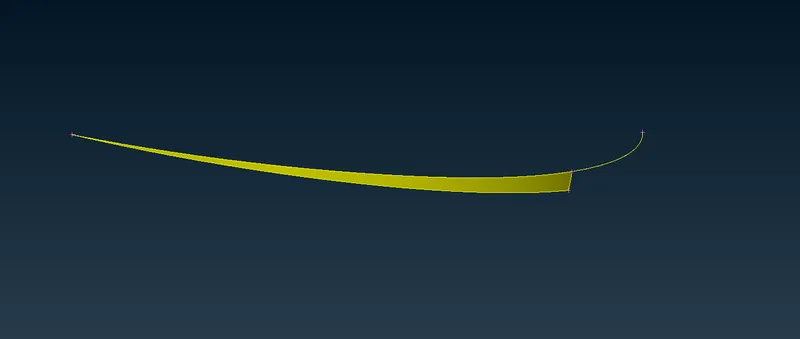
Inorder to clean those errors, we have two option in our hand. One is Manual fix and another one automatic fix. In this case, we Confidently gonna automatic fix, because as we noticed from the check tab which is "Yes" for "Auto fix".`
Inorder to do fix those thing in automatically, we have to select all errors which are shown up and right click to fix. Afterthat, ANSA algorithm quickly suppressed any one of double cons.
Once did those thing, we have to cross check the same model. Now, there's no error are popuped from the visible tab.
This Geometry is ready for next stage in the preprocessing which is middle surface extraction.
II) Extracting the middle surface from the parent component :
Middle surface means, a surface exactly created between the top & bottom surface from the parent component. It will helps us to reduce the computer calculating time and also reducing the storage space.
We have two option in our hand, one is automatic mid generation and another one manual middle surface generation.
If We take Automatic middle surface, it not possible to generate the mid surface properly in just single click. Since, it's thickness is varying different differently in each & every part.
So, we gonna manual mid surface by using few option in ANSA like Offset, Face Middle, Curve Middle etc.
i) Finding the similarity from the parent component :
As we noticely from given component as shown in below, there's symmetrical in shape about an plane except few surfaces. It will be like as shown in the below image.
If We generate the middle surface on half portion, then we gonna rotate the surface into the another portion by using rotation option under the translate gui, Which will helps us to saving the our time.
By using "Plane Cut" option under "faces" menu to which the geometry divide into two halfs.
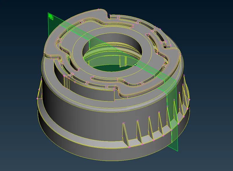
After Cut into two halfs, one half were looks like as shown in the below image.
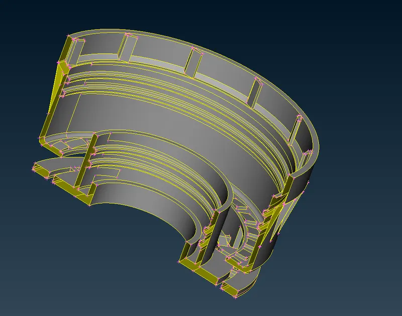
ii) Mid Surface Creation by using some tools :
Using Offset Option :
Make sure, we have check the appropriate thickness on a particular part before going to offsetting.
First of all, we have to select the "face offset" option under where "Topo" module. Followingly, select the surface which we gonna offset on it like as shown in below image.
Basically, a mid surface is created between exactly at neutral positon between top and bottom surface.
Put the offset distance which is half of thickness of parent component is 0.765. And press the middle mouse button, it will ask us to set the property card for that extracted particular surface and then apply it to appropriate PID.
Direction of middle surface extraction depends on orientation of the component surface.
Similarly, we have to do whereas the offset option is helpful to create the mid surface from the parent component as we seems steps in before.
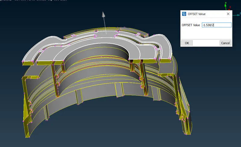
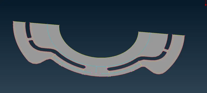
After Creating the mid surface for that particular part, it will looks like as shown in below image.
Using Face Middle option :
Select the Face "Middle" option from where "Topo" module. Followingly, select the two surface in proper manner like as shown in the below image.
Click the middle mouse button, it will ask to accept surface and subsequently ask to set the property card. After creating the new property card, a middle surface is created between at neutral position
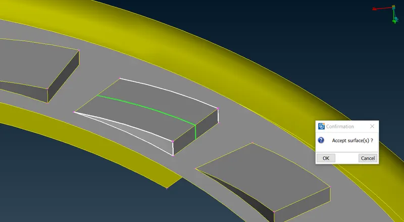
After creating the middle surface for teeth, it will looks like as shown in the below image.
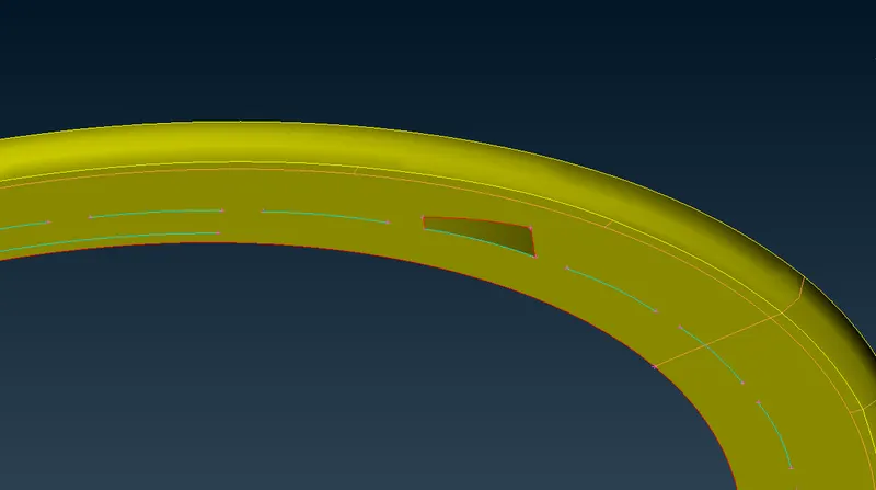
By Rotate option under the translate gui, we have to create the mid surface for remaining teeths as well instead of create a mid surface at each & every teeths.
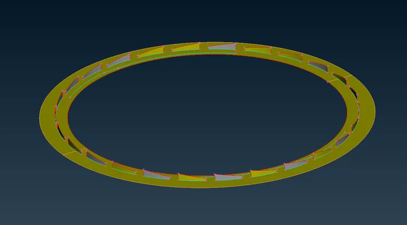
Make sure put the appropriate angle interval between the two teeths & put the appropriate number of teeths has been creating while perform rotate option.
Select the axis of rotation by help of two points which on about Y axis. Click middle mouse button to which perform rotate option.
After done the copy rotate operation, it will looks like as shown in the below image.
Using Curve Middle option :
Select the Curve "Middle" option under the "Topo" module, by select the two groups of doubles cons and press the middle mouse button to which creating the middle lines (Curve) between those two selected double cons in previously like as shown in below image.
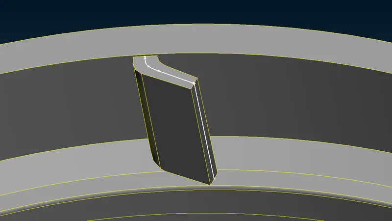
Once we create the curve, we have to create a surface by using any one of the options which are presented under "New faces" option under which "Topo" module.
Once we create the surface, we have to extend the surface to exact target surface as like in parent component. We can clearly see the triple cons are created, because sharing surfaces are morethan two.
After completion of all the process, it looks like as shown in the below image.
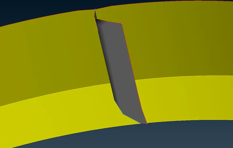
By using Rotate option to which copying the inner grip to the remaining place where ever need it.
iii) Final Half Middle surface :
This is the half of the mid surface, we have to copy & rotate it about an Y axis to get the full mid surface.
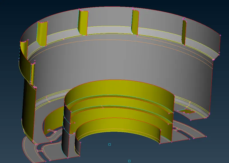
After done the copy & rotate process, a full mid surface has captured like as shown in below image. Followingly, topo it for which connects the two halfs.
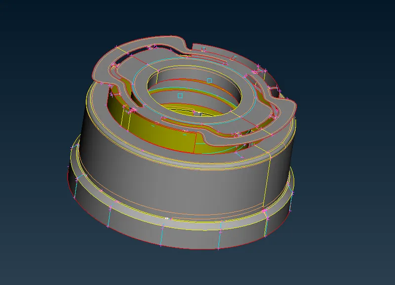
III) Quality Parameter and Mesh Element Parameters :
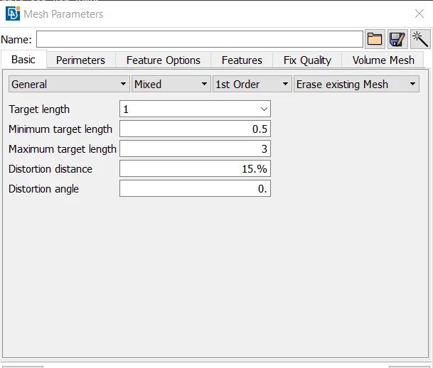
We have to give the quality parameter which are Target length, minimum target length and maximum target length like as shown in the below.
A Meshing algorithms will distrize the model with respect to given this values.
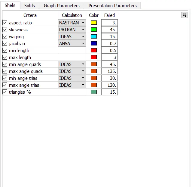
Make sure set the quality criterias which will help us to visualize finite element model whether it's fails any of these or not.
IV) Perform Meshing Operation :
Basically, To divide the entire model into infinitesimal control volume, that framework is called meshing. This process is called discritization.
Make sure set the resolution for which two node distance between is equal to target element length.
ANSA have varieties option for which descritize the entire model, each and every meshing option have different algorithm. In this case, we have to use "Best" option to which generating the FE's on a each & every surface.
Select the any suface, click middle mouse button to which elements are creating. If created elements are improper, we have remeshing on a elements by using "Improve" or "reconstruct" option.
Also, While doing on meshing, we have keep in mind about element qualities. If any elements are failing due to any one of the parameter, we have takecare on that element untill or unless element should not failing.
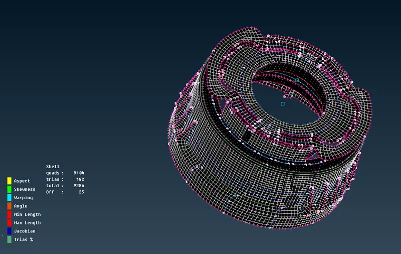
In this case, some elements are failing due the proximity of triple cons. There's unavoidable.
After done meshing on a whole surface, it will look like as shown in the above image.
V) Assigning the thickness :
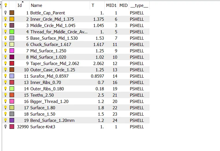
Inorder to assigning the thickness, make sure we put the appropriate thickness values to the corresponding property identities like as shown in below image.
Without thickness assigning :
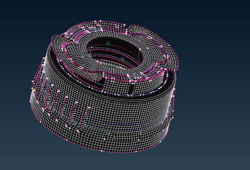
With thickness assigning :
Inorder to visualize the thickness from the finite element model, we have check the "Draw shell as solids" option under which "Presentation parameters" and then apply on it.
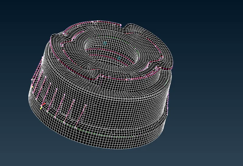
CONCLUSION :
Successfully done the preprocessing operation on a given Bottle cap model like Checking the geometry error from the model, Middle surface Extraction from the parent component, Meshing and then assigning the thickness to the middle surface.