Washing Machine & Gear Shift using state flow using simulink
1.To implement control logic of a “washing machine” using Stateflow as per given sequence:
Conditions:-
- If the power supply is available, the system gets activated
- If the Water supply is not available, stop the process & indicate through LED
- Soaking time should be 200s followed by Washing time of 100s.
- Then rinsing happens for the next 20s & dryer runs for 50s
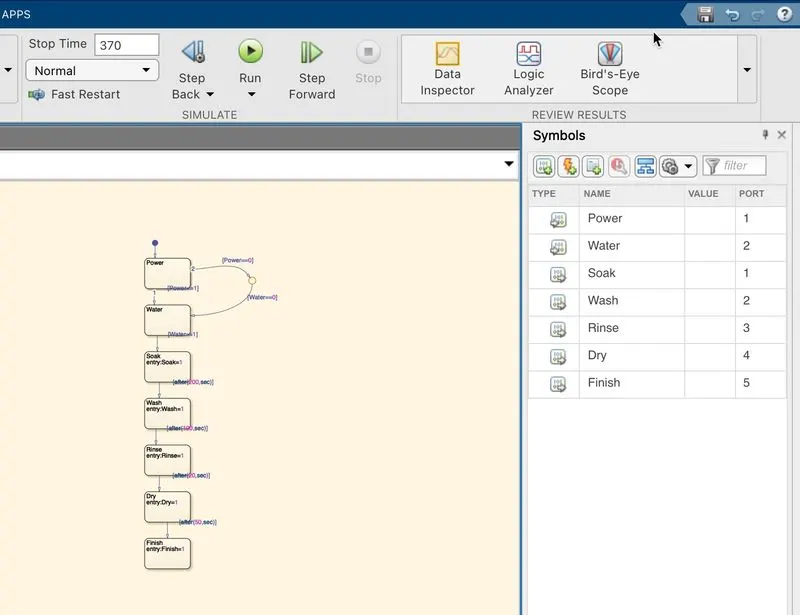
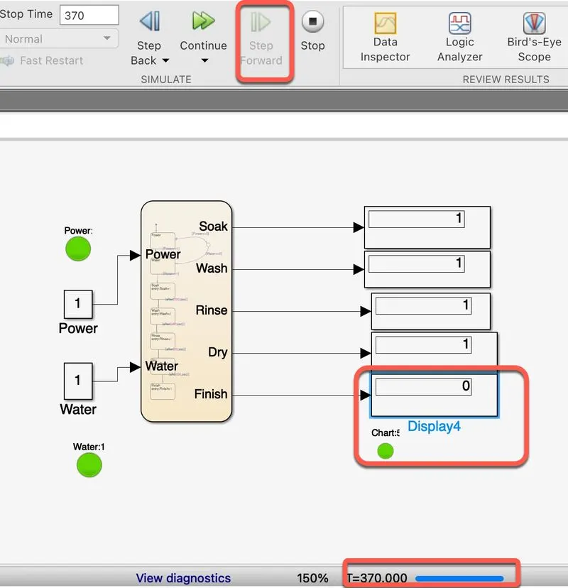
- In order to showcase the state flow, the washing inputs are fed inside the blocks namely Power, Water whereas Soak, Wash, Rinse, Dry & Finish remain the outputs.
- Power and water are connected with a junction block so that if either doesn't operate the washing machine shouldn't work.
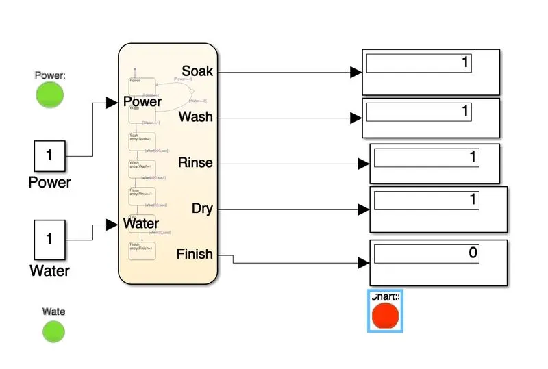
- The Inputs Power and Water are given with constants.
- Now the Individual time taken is calculated
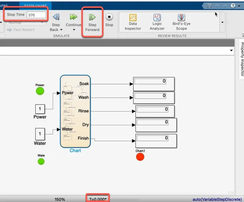
- Stop time is taken as 370 seconds, where the display is 0 with T=0 at each process.
- Stop time is the combined time for the whole process from Soak to Finish.
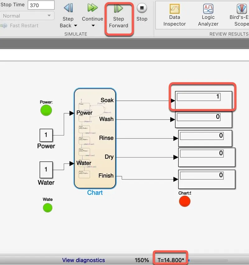
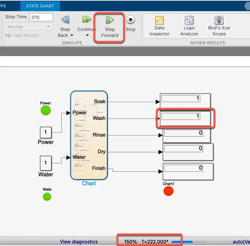
- for T=14.8* Soak is done, later after 222* seconds next is the wash is completed
- similarly at 325.6* Rinse followed by Dry at T=346.8* are completed
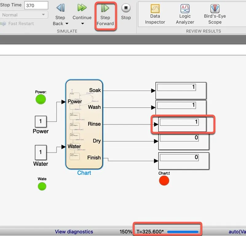
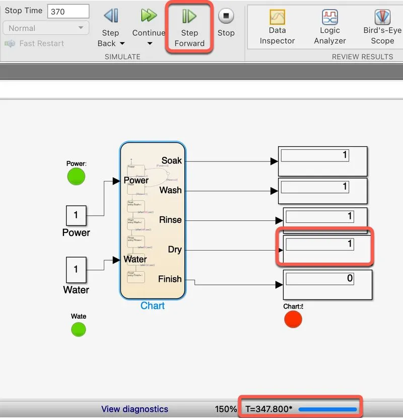
- Finally, at T = 370 seconds, the process is complete.
2. To make a Simulink chart for the “Gear shift” logic as per the below conditions:
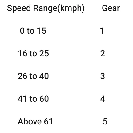
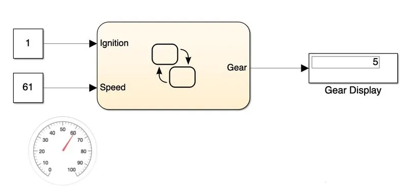
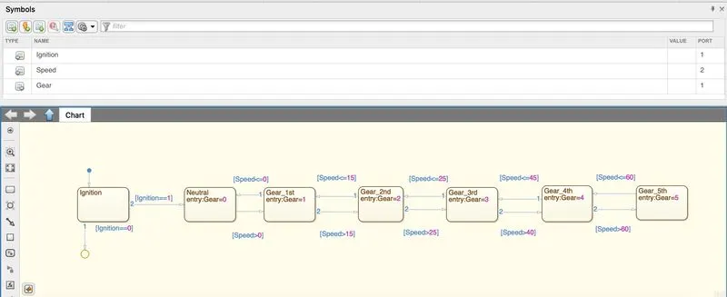
- Here the state flow if designed in such a way that the gears are displayed with varying speeds
- Above conditions are fed inside the chart
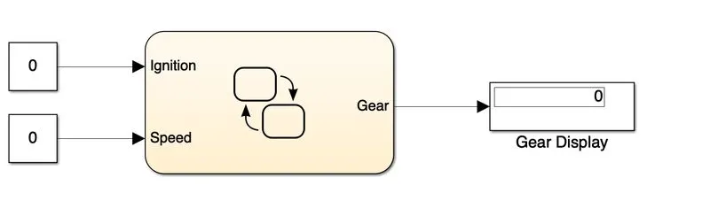
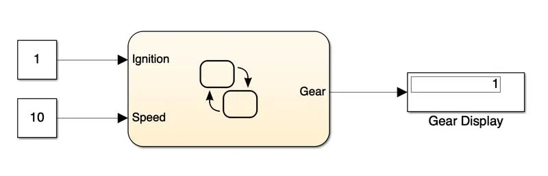
- Ignition, Speed are Inputs
- Gear is Output.
- Consider Ignition & Gear as 0, as there is no input the Gear Display is also 0 after running the simulation.
- For speed = 10, the display gear is 1. It satisfies the condition 0-15 kmph in the 1st Gear.
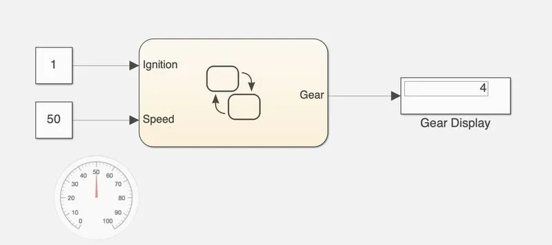
- For speed = 50, the display gear is 5. It satisfies the condition 41-60 kmph in the 4th Gear.
- Here Gauge is linked with the Speed Contant Block.
- consider speed=61, display gear is 5. It satisfies the condition 61 & above kmph in the 5th Gear.