Week - 4
1.AIM
To Implement control logic of a “washing machine” using Stateflow as per given sequence:
- If the power supply is available, the system gets activated
- If the Water supply is not available, stop the process & indicate through LED
- Soaking time should be 200s followed by Washing time of 100s.
- Then rinsing happens for the next 20s & dryer runs for 50s
BLOCKS USED
- Chart - Using this we can make Stateflow
- constant - This block generates a constant value for power and water supply
- display - Show the value of the output
- lamp - this block used to indicate the state of the process while we connect with the respected block
- toggle switch - these blocks used on and off the power and water condition these blocks are connected to the constant block
PROCEDURE
Double click the chart block to open the Stateflow environment. then choose the state block
as the given condition we create a Stateflow chart as following which shows the step by step process of washing machine
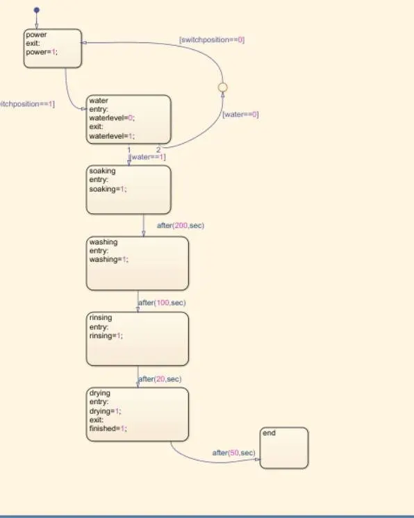
1. we can see the above image here switch position and water are the input data and the process can move from first state block to second state block only if switch position is equal to 1 which is on position. so that we can see the result in the display of power as 1 when switch position in on.
2. then switch on the water supply to move further process like soaking and washing if water switch off the process returned to state one.
3. in the third state soaking process occurs for 200-second then moved to the fourth state.
4.in the fourth state washing process occurs for 100 sec then moved to the fifth state.
5.in the fifth state rinsing process occurs for 20 sec then moved to the sixth state.
6. in the sixth state drying process occurs for 50 sec and finishes the process and moved to the end state.
in the Simulink environment connects constant blocks to the input ports and connect the display blocks to the output port and the merge the lamps and switches to the respective blocks then run the simulation for 400 sec had been finished stage.
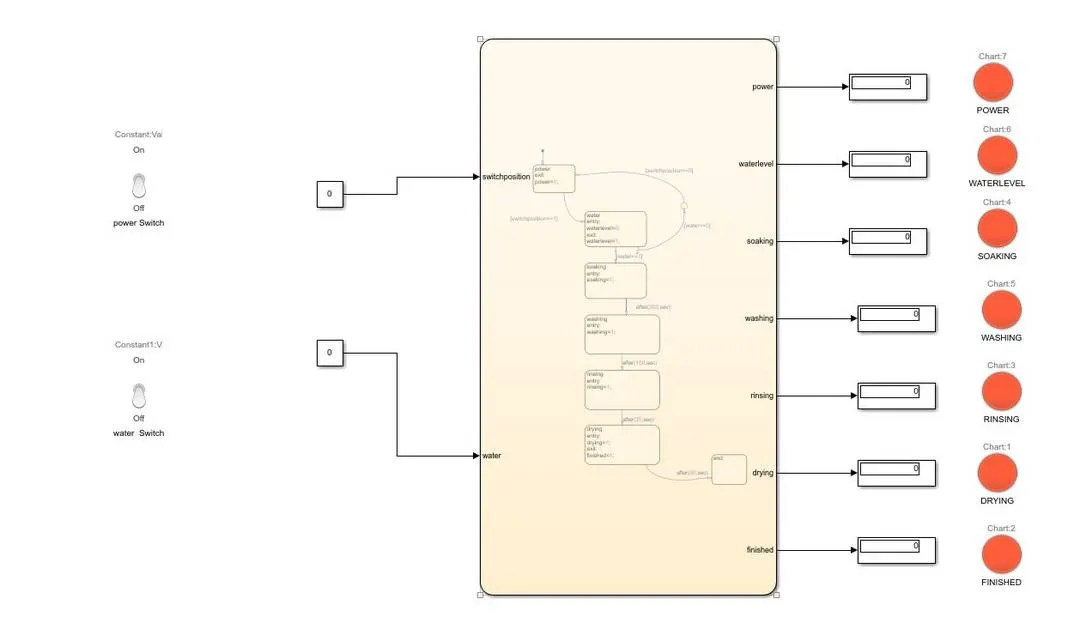
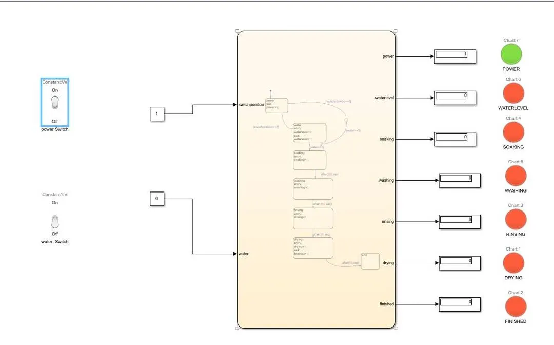
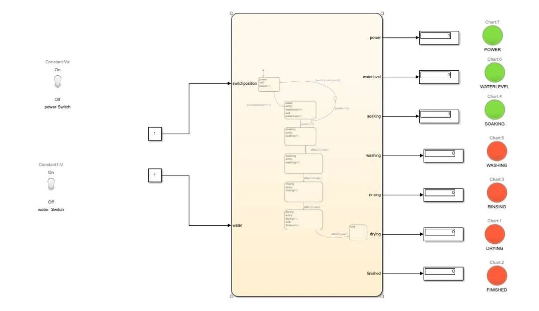
when we run the model for varies seconds the following outputs will come.
WHEN POWER=0,WATER=0:
WHEN POWER=1,WATER=0:
WHEN POWER=1,WATER=1 RUN FOR 200 sec:
WHEN POWER=1,WATER=1 RUN FOR 300 sec:
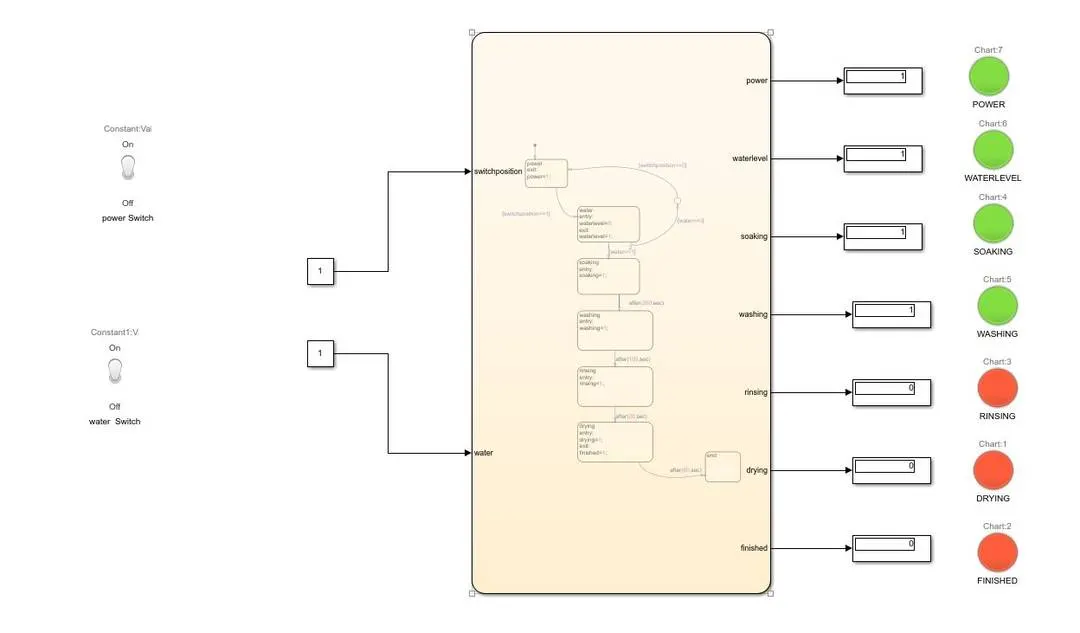
WHEN POWER=1,WATER=1 RUN FOR 320 sec:
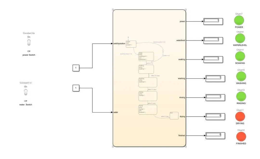
WHEN POWER=1,WATER=1 RUN FOR 370 sec:
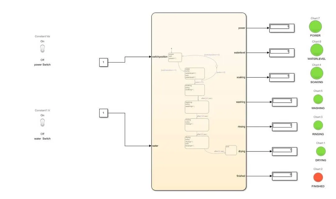
WHEN POWER=1,WATER=1 RUN FOR 400 sec:
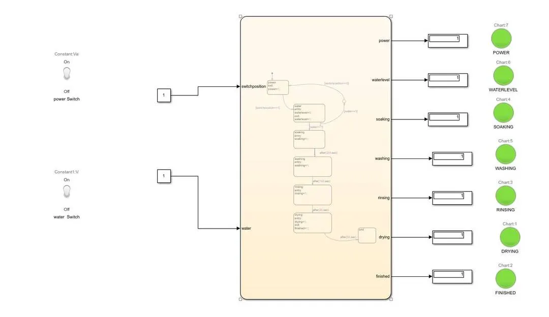
CONCLUSION:
Thus the Implement control logic of a washing machine using Stateflow have been done.
-----------------------------------------------------------------------------------------------------------------------------------------------------------------------------------------------------
2.AIM
To Make a Simulink chart for the “Gear shift” logic as per below conditions:
Speed Range(kmph) Gear
0 to 15 1
16 to 25 2
26 to 40 3
41 to 60 4
Above 61 5
Give speed input while the simulation is running & display the gear number.
BLOCKS USED
- Chart - Using this we can make Stateflow
- constant - This block generates a constant value for power and water supply
- display - Show the value of the output
- lamp - this block used to indicate the state of the process while we connect with the respected block
- toggle switch - these blocks used on and off the power this block is connected to the constant block
PROCEDURE
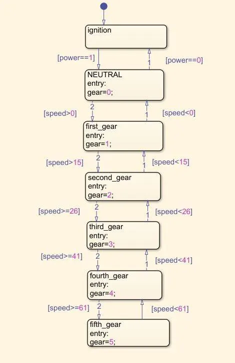
1. Before we start we have to analyse the input and output of the system here is power and speed are the inputs and gears are output.
2.The following image which shows the process of system.
3.In the second state block, here the neutral gear is comes after the ignition only if power is given.
4.In the third state block ,When the speed is greaterthan zero the gear is changes from neutal to first gear.
5.In the fourth state block ,If the speed is greaterthan 15 the gear changes from first to second gear.
6.In the fifth block ,if the speed is greaterthan or equal to 26 gear changes from second to third gear.
7.In the sixth block ,if the speed is greaterthan or equal to 41 gear changes from third to fourth gear.
8.In the seventh block, If the speed is greaterthan or equal to 61 gear changes from fourth to fifth gear.
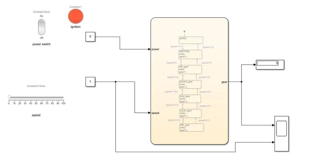
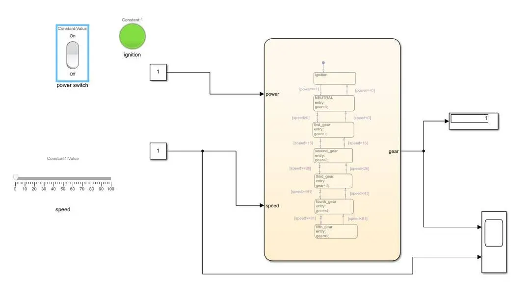
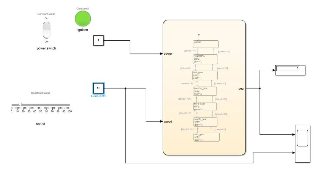
then in simulink environment we have to connect the switches and lamps to the respective input blocks.
THE OUTPUT
When POWER=0,SPEED =1:
When POWER=1,SPEED =1:
When POWER=1,SPEED =15:
When POWER=1,SPEED =25:
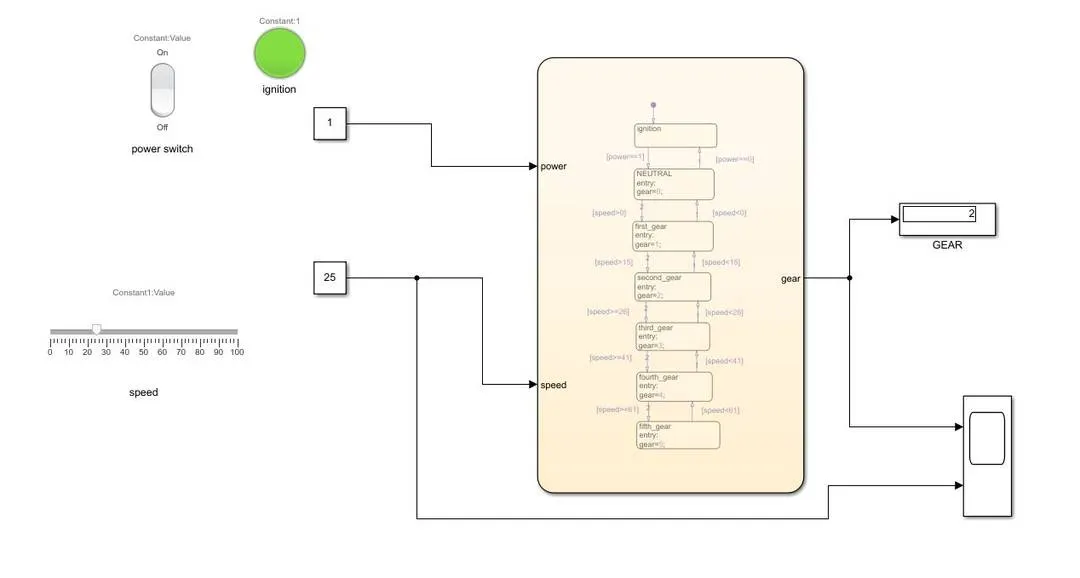
When POWER=1,SPEED =35:
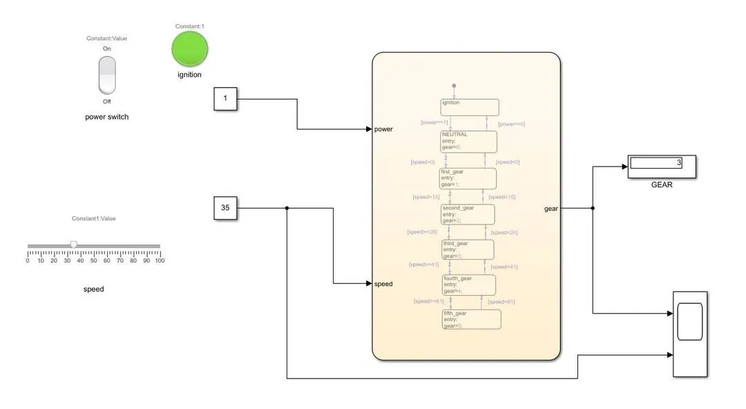
When POWER=1,SPEED =55:
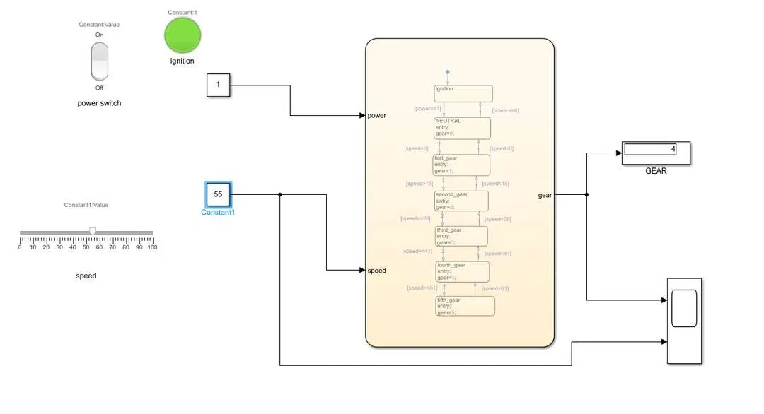
When POWER=1,SPEED =100:
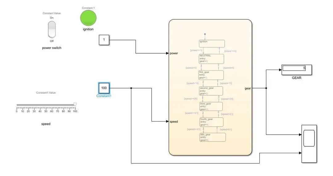
CONCLUSION
Thus the Making a Simulink chart for the “Gear shift” logic as per given conditions have been done.