Week 3 Verification of Weld Joints
Objective: In this study simulation of weld joint has done. This study compares the results at different material of weld.
Case 1. Stainless Steel: In this case, the material of the plates must also be the same. Use Stainless steel for both weldments and plates. No need to add flux to the weldments.
Case 2. Aluminium Alloy: The material to be chosen for this case is Aluminium alloy (high strength, wrought). [Plate material to be used is stainless steel]
Case 3. Bronze: In order to simulate "Brazing", you should be using bronze as the weld material. Assign Stainless Steel to both plates and Copper to the "Ribs".
The outcomes results are Equivalent stress, strain, total deformation and life, This study is done in Ansys 2022
Introduction:
Welding is a fabrication process that joins materials, usually metals or thermoplastics, by using high heat to melt the parts together and allowing them to cool, causing fusion. Welding is distinct from lower temperature techniques such as brazing and soldering, which do not melt the base metal (parent metal).
Brazing: Brazing is a metal-joining process in which two or more metal items are joined together by melting and flowing a filler metal into the joint, with the filler metal having a lower melting point than the adjoining metal. Brazing differs from welding in that it does not involve melting the work pieces.
- Borax is used as filler in brazing, Borax improves the flow of filler metals and reacts with certain oxides to lower their melting points.
- Brazing processes run at temperatures between 426.667°C and 1093°C
Procedure:
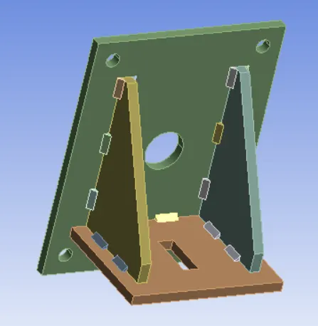
1.Geometry
- Input the model as Step format in geometry
2.Material assignment
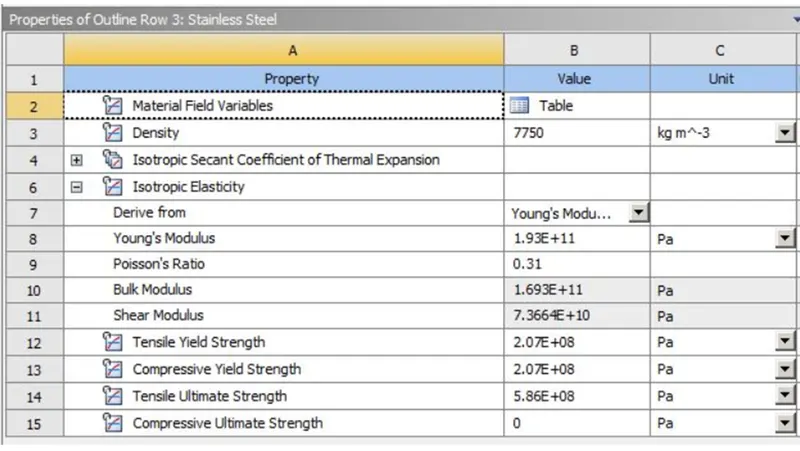
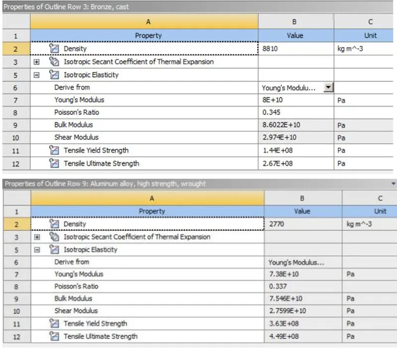
- Open Engineering Materials and select the required material.
- Stainless steel is used as material in ANSYS of given material and other comparing materials are aluminum alloy, Bonze
3.Meshing
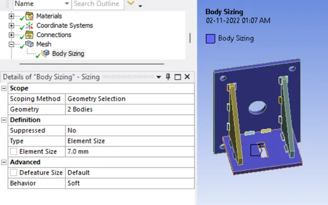
- For Meshing the body element size =7mm
4.Boundary condition
Connection
1.Contact creation
(a)
- Select the faces of gear teeth which will be in contact during simulation running
- Definition > type - Frictional
- Advanced > Formulation - Program controlled
- Geometric Modification > Interface Treatment - Add offset Not ramping
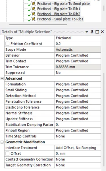
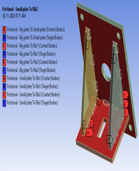
- All other weld contacts are Bonded
2.Analysis Setting
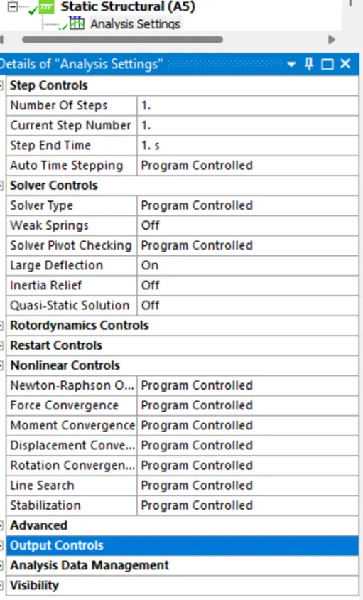
- Fixed support (Insert by right click on analysis setting)
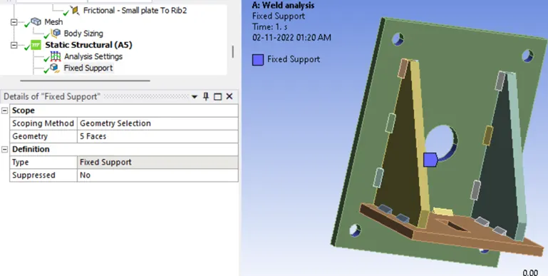
4.Force condition
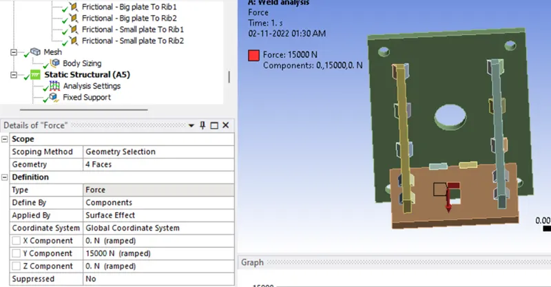
Results (output):
Mesh
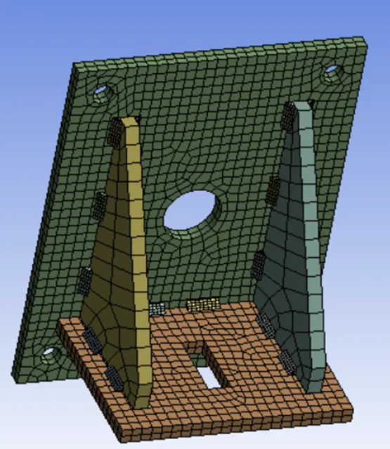

Meshed Quality: According to mesh matrics the Quality vary from 0 to 1
0 for poor Quality element
1 for best Quality element
In our case Mesh of maximum element lies in between 0.9 to 1 so it is good as per Quality scale

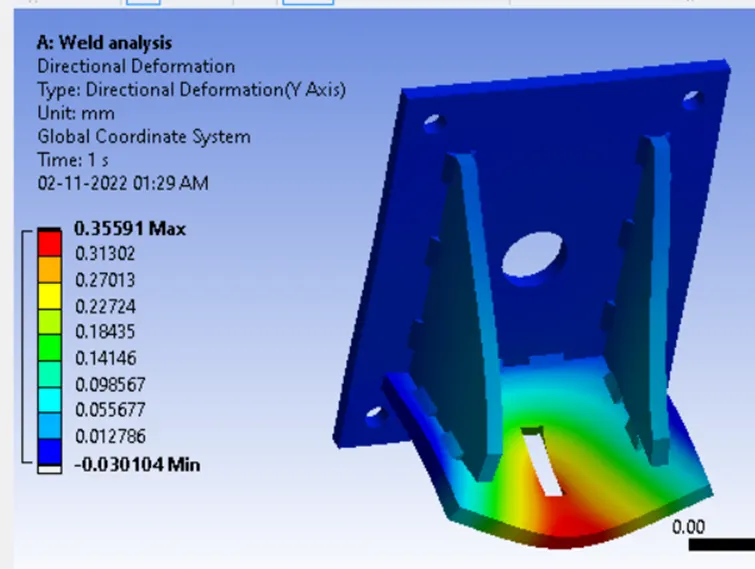
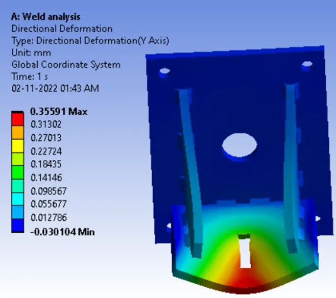
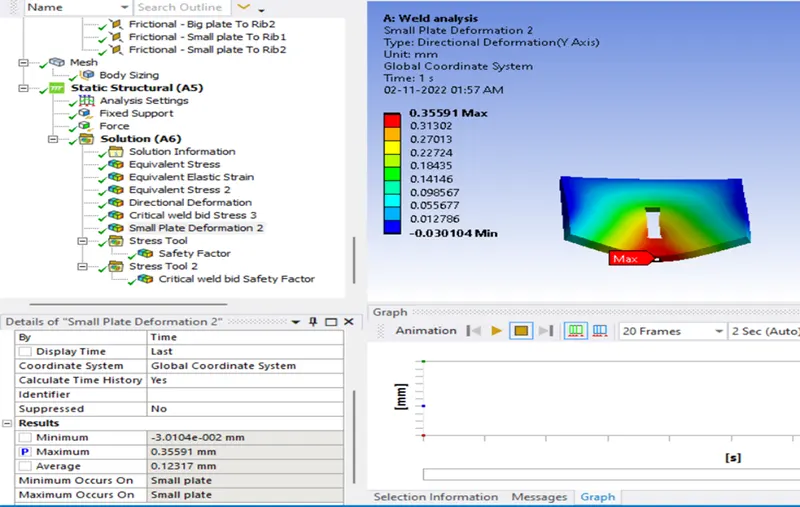
Deformation
Max deformation= 0.3559mm
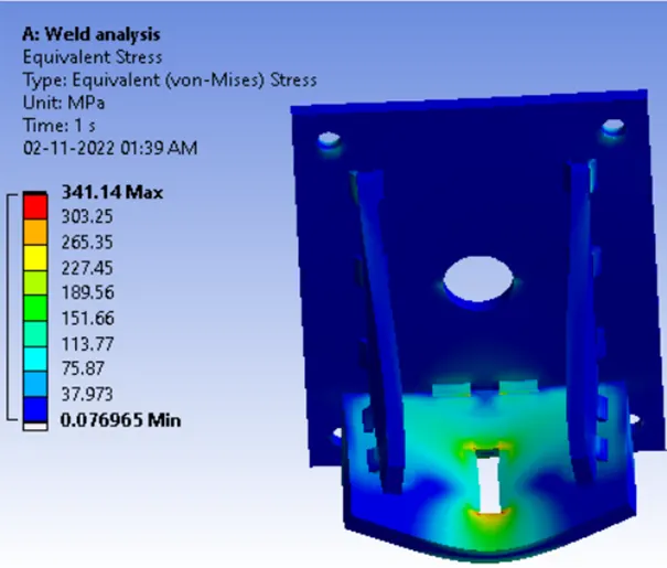
Stress (stress of whole product)
Max stress= 341.14Mpa
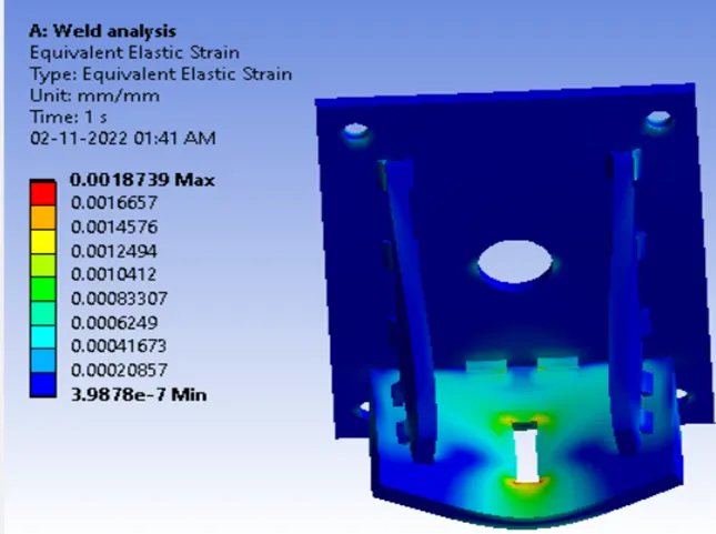
Strain (strain of whole product)
Max Strain =0.0018739 mm/mm
Directional deformation (Directional deformation of whole product)
Max=0.35591mm
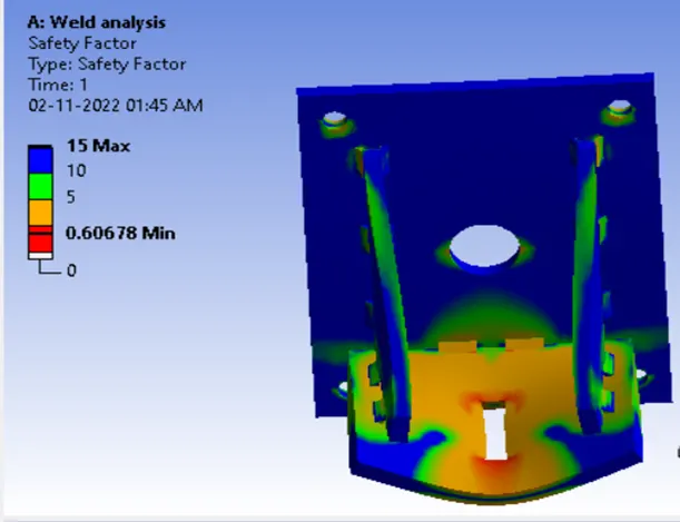
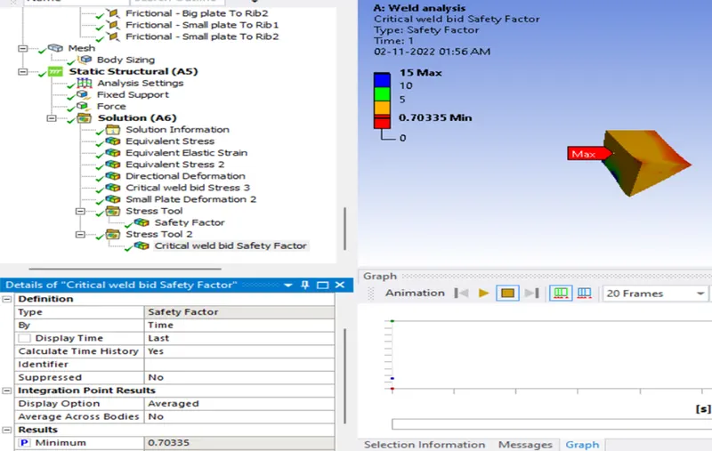
Factor of safety result
Minimum = 0.6
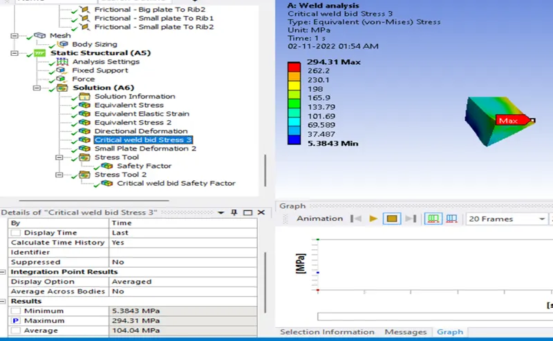
Stress (Stress of weld bid)
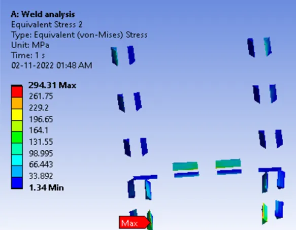
Now study to the seprate critical stressed weld bid joint
Factor of safety ( critical weld bid)
Deformation result of small plate
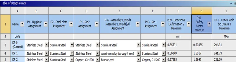
Now compare these results for different material condition by parametric study by selecting the P symbol as above results which will required for comparing.
Conclusion:
By comparing the result, the study shows that in design point1 (DP1) weld bid as aluminum alloy has maximum factor of safety 1.5017 among the all material so it is best for the welding the component among all.