Week 3 Verification of Weld Joints
AIM: - TO PERFORM STATIC STRUCTURAL ANALYSIS OF THE WELDED JOINT FOR THREE DIFFERENT WELDING MATERIALS AND COMPARE DIRECTIONAL DEFORMATION, EQUIVALENT STRAIN, AND THE MAXIMUM STRESS IN WELDS IN EACH CASE.
Objectives:
Perform Static Structural analysis on the given welded joint for three different weld materials.
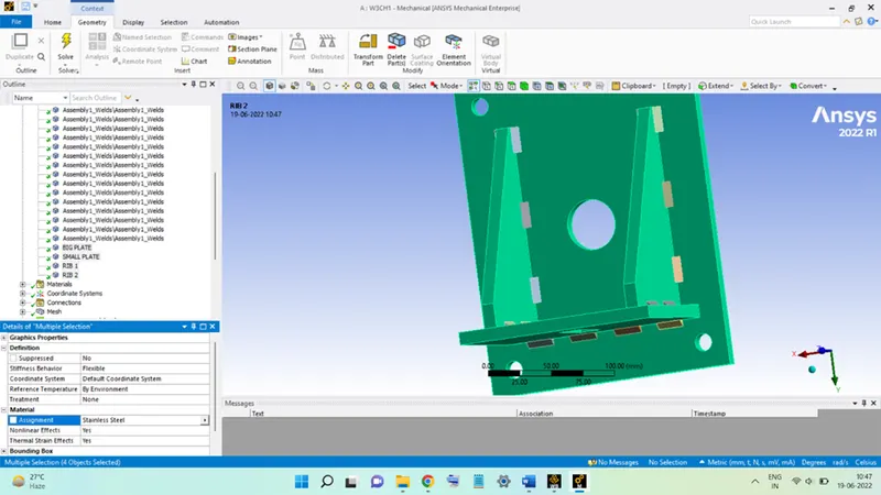
Case 1: STAINLESS STEEL as the weld material as well as the plates and ribs.
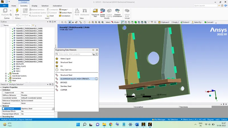
Case 2: ALUMINIUM ALLOY (High Strength, Wrought) as the weld material and STAINLESS STEEL as the material for plates and ribs.
Case 3: BRONZE as the weld material, STAINLESS STEEL for plates, and COPPER for the ribs.
To begin with, the analysis, launch the Ansys Workbench and select the Static Structural Analysis from the Analysis Systems. Next is to import the geometry into the project.
the geometry after import will look like this in the SpaceClaim:
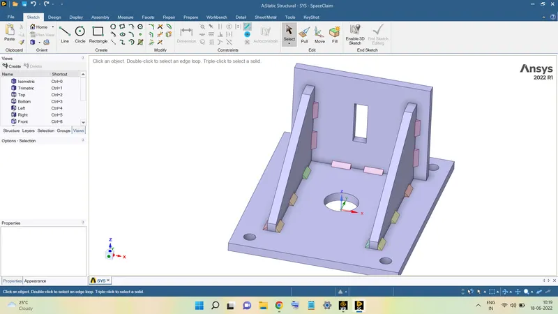
The steps taken to set up the analysis are as follows:
Adding Material to projects:
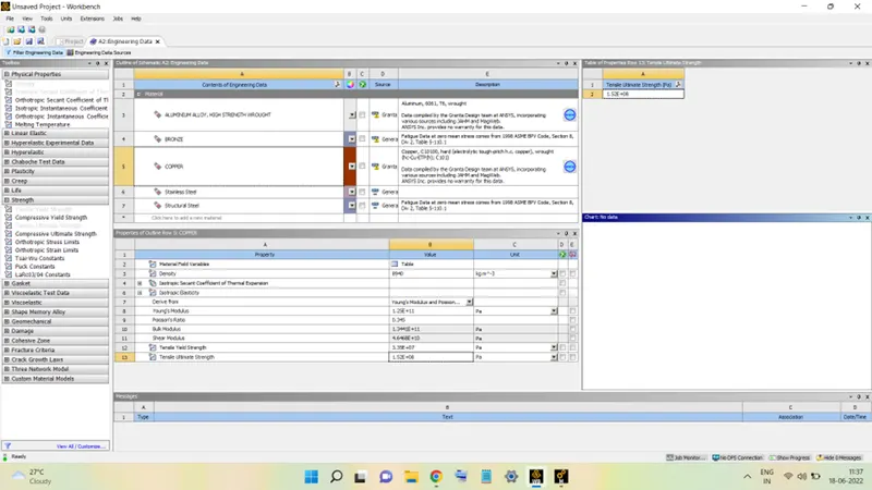
To add the required materials to the project, double-click on Engineering Data, then select the required materials if present in the Engineering Data Sources. If the materials are not present then manually add the materials to the project.
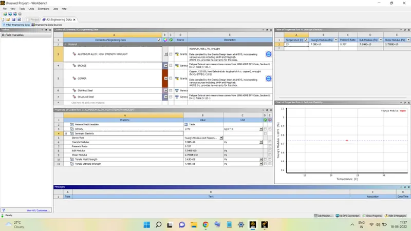
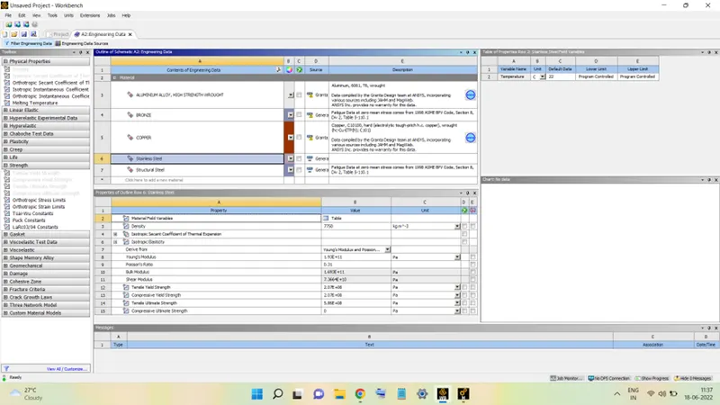
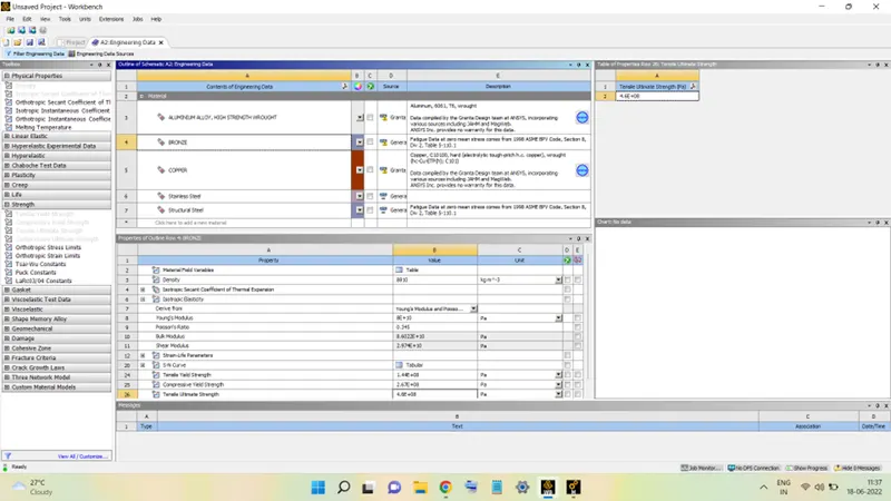
The materials with their respective properties data are shown below:
Aluminium Alloy
Stainless Steel:
Bronze:
Copper:
Assigning Contact Properties to Geometry:
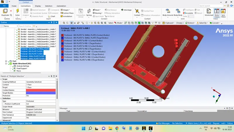
Go to Connections, and double-click Contacts. Now select the last 5 contacts and click Rename Based on Definition.
Then assign the Type as Frictional and set Friction Coefficient 0.2.
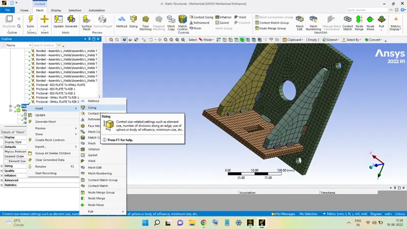
Next is to apply the Meshing to the geometry. Right-click on Mesh, and select Sizing. Select the BIG PLATE and SMALL PLATE and click Apply. Set the Element Size to 7 mm and click on Generate Mesh.
Assigning the Analysis Settings:
The load of 15000 N is applied to the rectangular hole in a single step.
Turn ON the Large Deflection and the rest are kept to default settings.

The analysis is ready to run, click Solve to begin the analysis.
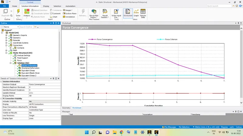
The Force Convergence plot is shown below:
RESULTS:
CASE 1: STAINLESS STEEL AS MATERIAL FOR ALL COMPONENTS.
Deformation in Y-Direction:
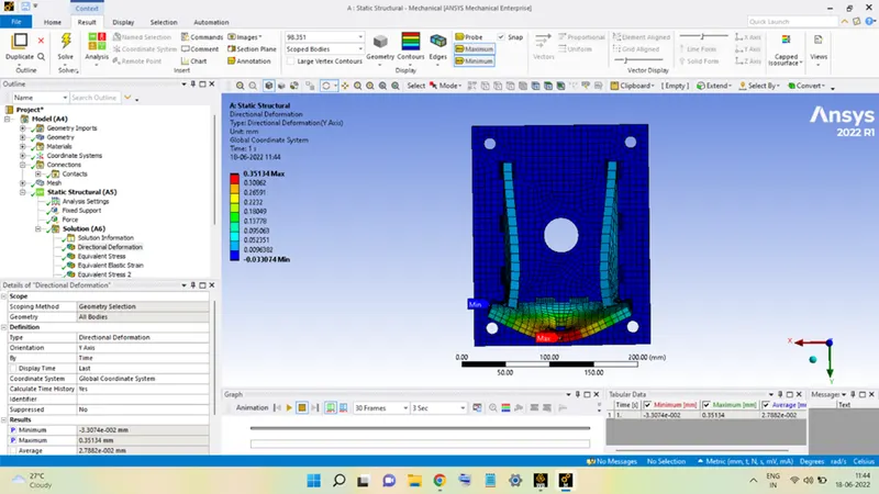
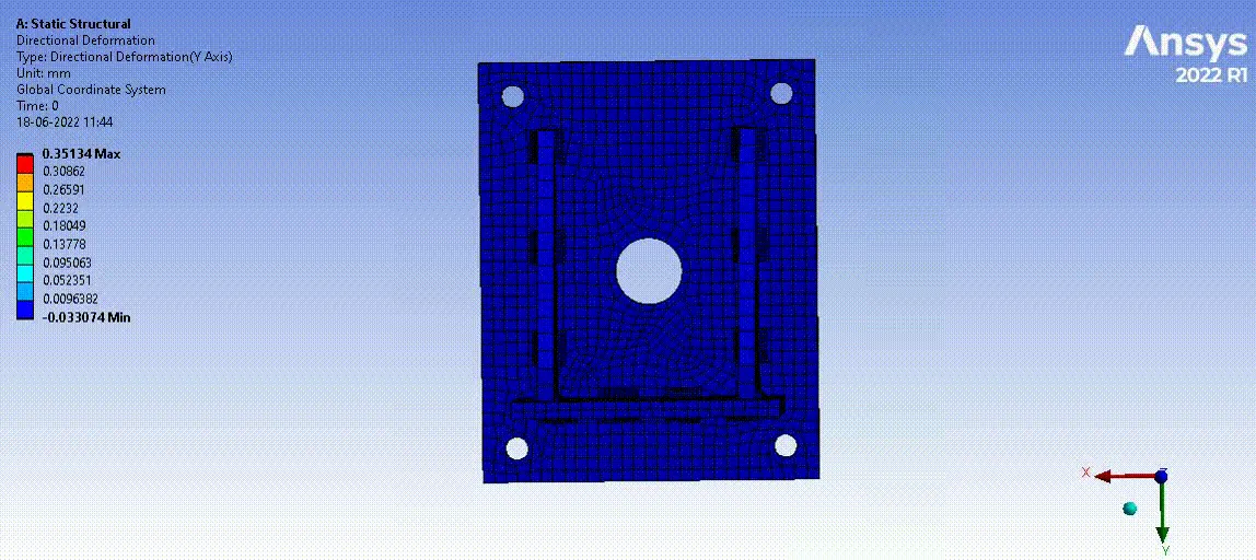
the above figure shows the behavior of the joint for the given loading condition.
The maximum deformation is seen to be occurring in the SMALL PLATE equal to 0.35134 mm.
Stress in Joints:
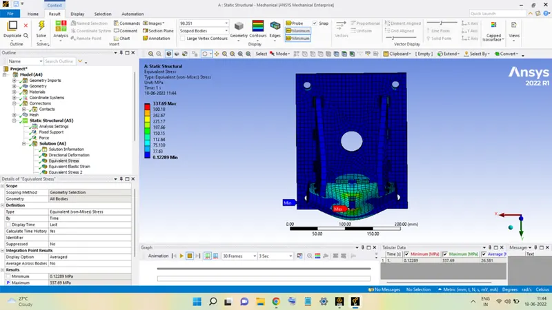
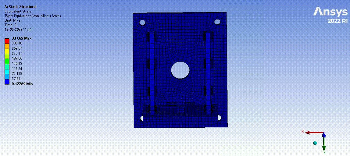
The above figure shows the stress distribution in the whole joint due to the load acting.
Again, the maximum stress is seen to be present on the SMALL PLATE equal to 337.69 MPa.
Strain in RIBS:
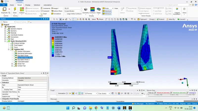
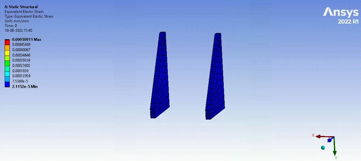
The above figure shows the strain distribution in the two RIBS of the joint due to the load acting.
The maximum strain is seen to be present in the RIB on the left equal to 5.0911 x 10⁻⁴.
Stress in Welds:
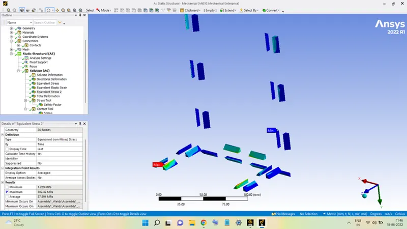
The above figure shows the stresses present in the WELDS alone due to the load acting on the joint.
The maximum stress acting is equal to 302.42 MPa.
Safety Factor in Welds:
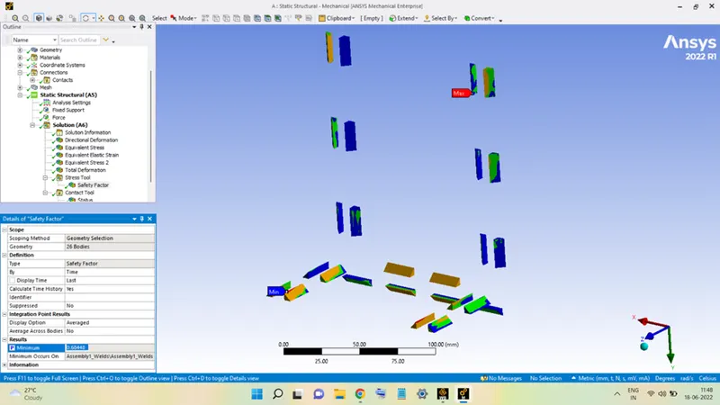
The above figures show the Safety Factor prevailing in the WELDS for the given loading condition. Most of the welds are having a decent value of the safety factor, but some of the welds are having less than the unity value of the safety factor.
The minimum value is equal to 0.68448.
Contact Status:
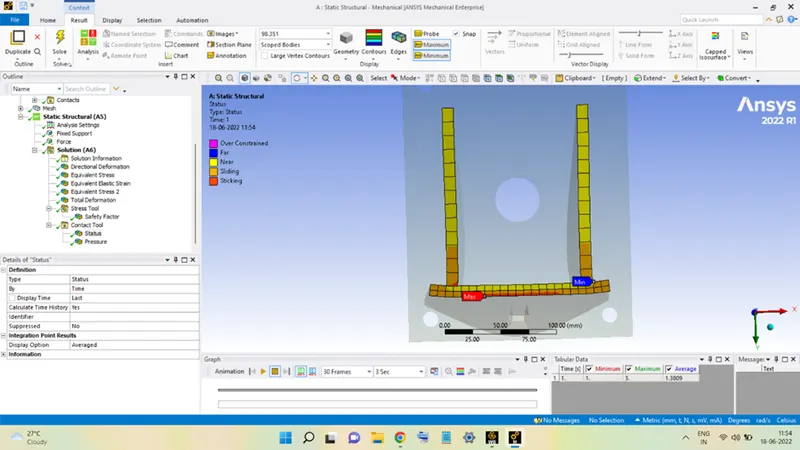
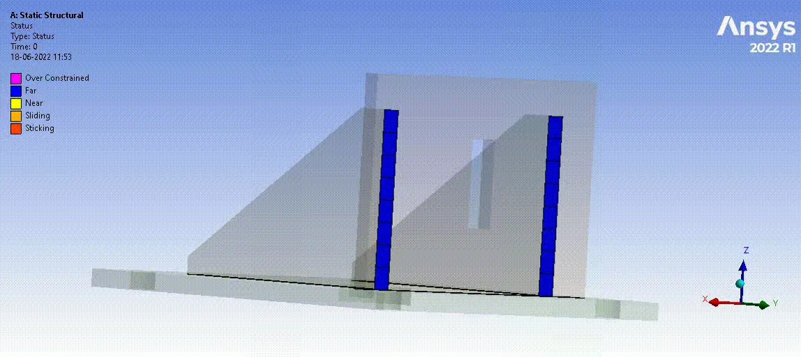
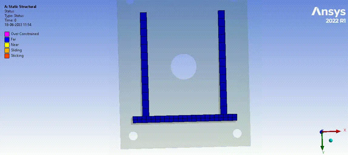
The behavior of the frictional contacts in the joint can be seen in the figures shown above. There is sticking contact in some regions, and in a few regions, the sliding and the near-contact are present.
Contact Pressure:
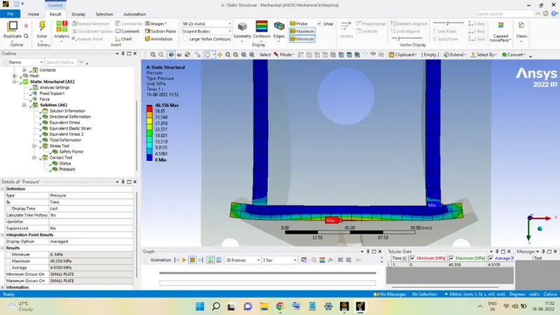
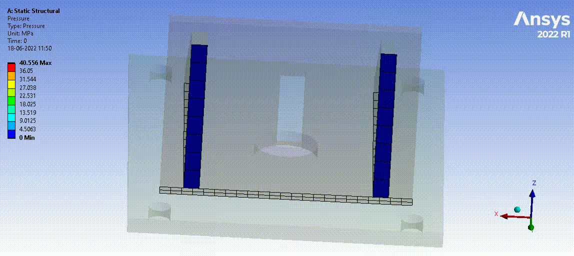
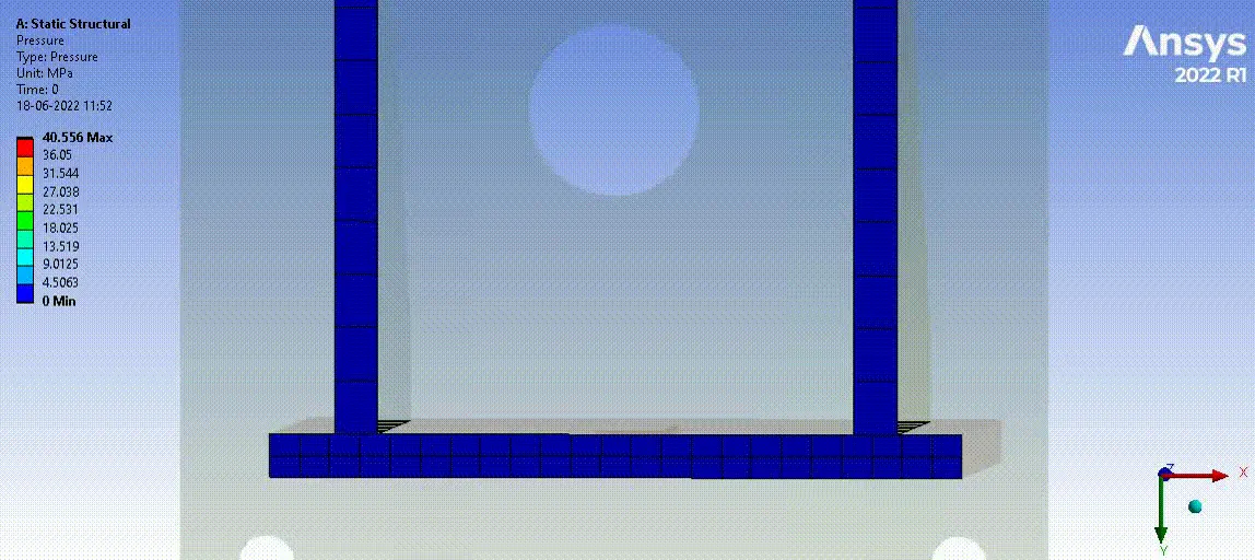
The pressure developed between the frictional contacting surfaces is shown above. Most of the contact regions are under low values of pressure, but in SMALL PLATE the pressure is seen to be reaching a maximum value of 40.556 MPa.
CASE 2: WELD MATERIAL IS TAKEN AS ALUMINIUM ALLOY:
Deformation in Y-Direction:
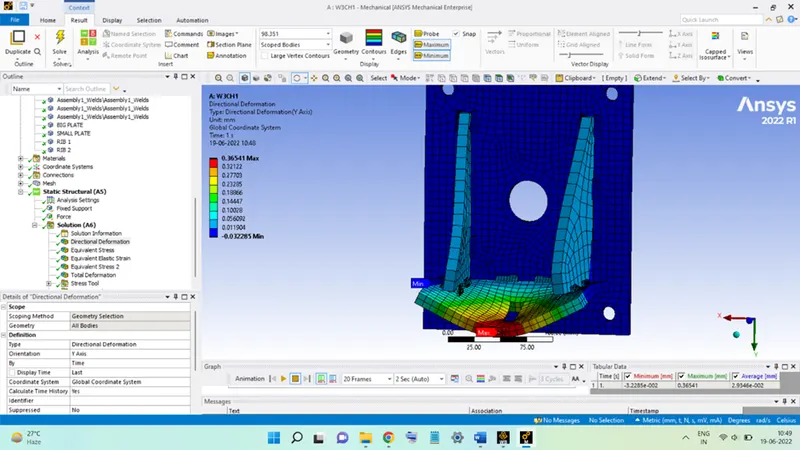
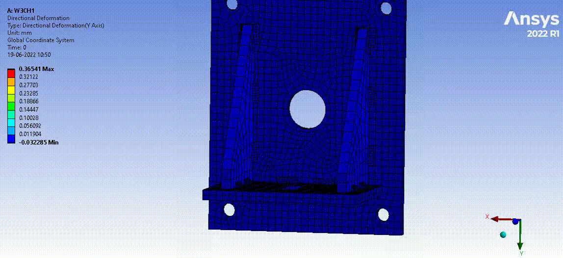
the above figure shows the behavior of the joint for the given loading condition.
The maximum deformation is seen to be occurring in the SMALL PLATE equal to 0.36541 mm.
Stress in Joint:
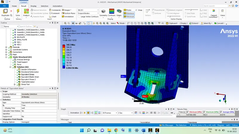
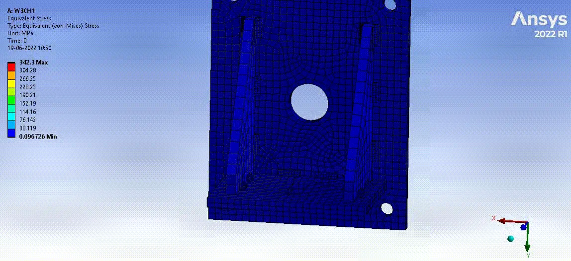
The above figure shows the stress distribution in the whole joint due to the load acting.
Again, the maximum stress is seen to be present on the SMALL PLATE equal to 342.3 MPa.
Strain in RIBS:
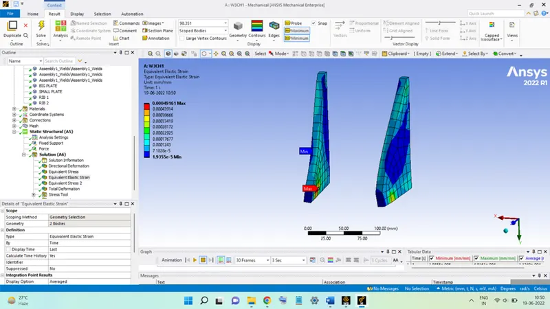
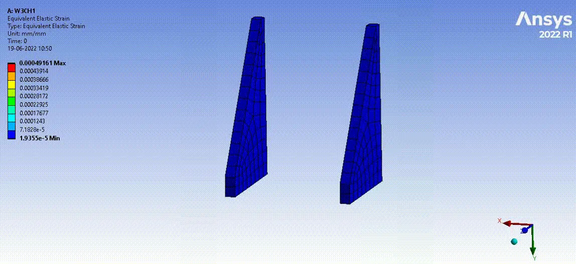
The above figure shows the strain distribution in the two RIBS of the joint due to the load acting.
The maximum strain is seen to be present in the RIB on the left equal to 4.9161 x 10⁻⁴.
Stress in Welds:
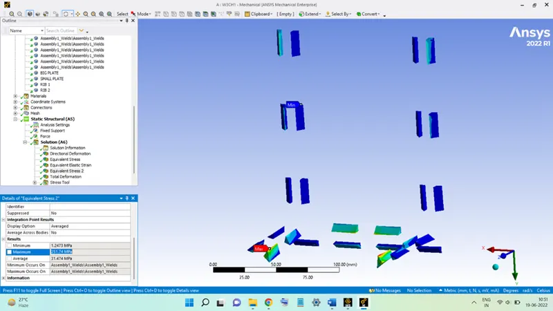
The above figure shows the stresses present in the WELDS alone due to the load acting on the joint.
The maximum stress acting is equal to 251.74 MPa.
Safety Factor in Welds:
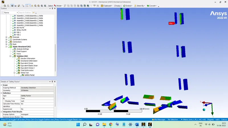
The above figures show the Safety Factor prevailing in the WELDS for the given loading condition. Most of the welds are having a decent value of the safety factor, but some of the welds are having less than the unity value of the safety factor.
The minimum value is equal to 1.442.
Contact Status:
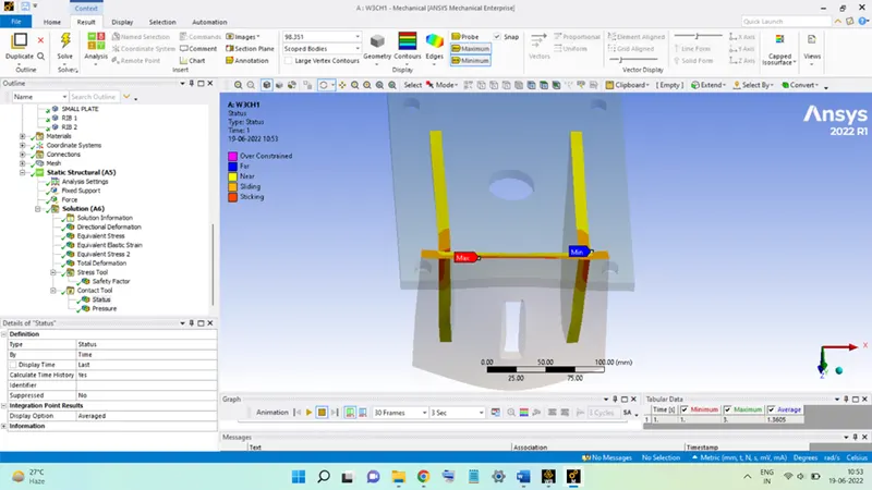
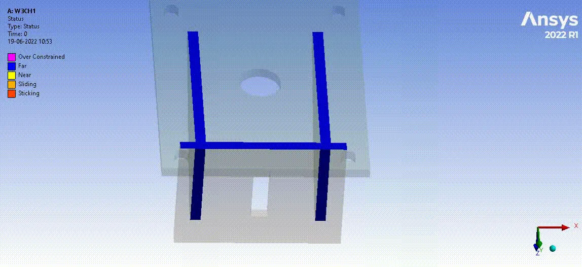
The behavior of the frictional contacts in the joint can be seen in the figures shown above. There is sticking contact in some regions, and in a few regions, the sliding and the near-contact are present.
Contact Pressure:
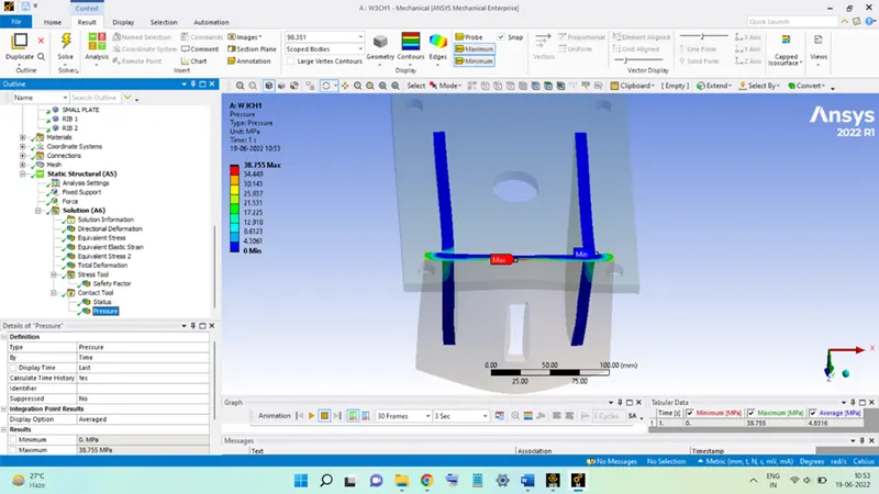
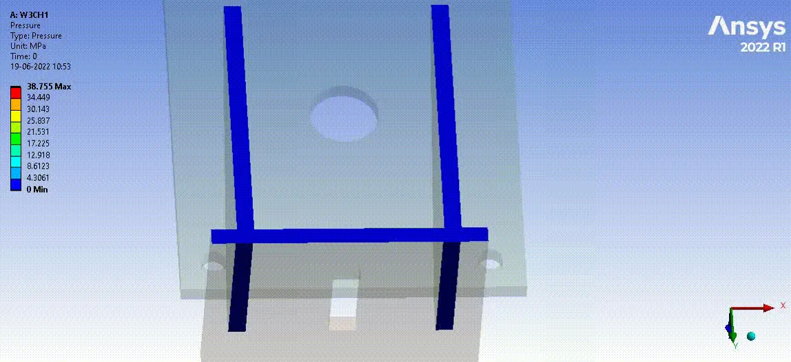
The pressure developed between the frictional contacting surfaces is shown above. Most of the contact regions are under low values of pressure, but in SMALL PLATE the pressure is seen to be reaching a maximum value of 38.755 MPa.
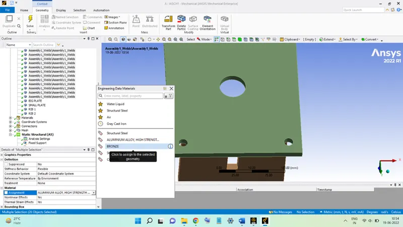
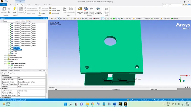
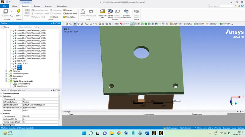
CASE 3: WELD MATERIAL IS TAKEN AS BRONZE ALLOY AND COPPER FOR RIBS:
Deformation in Y-Direction:
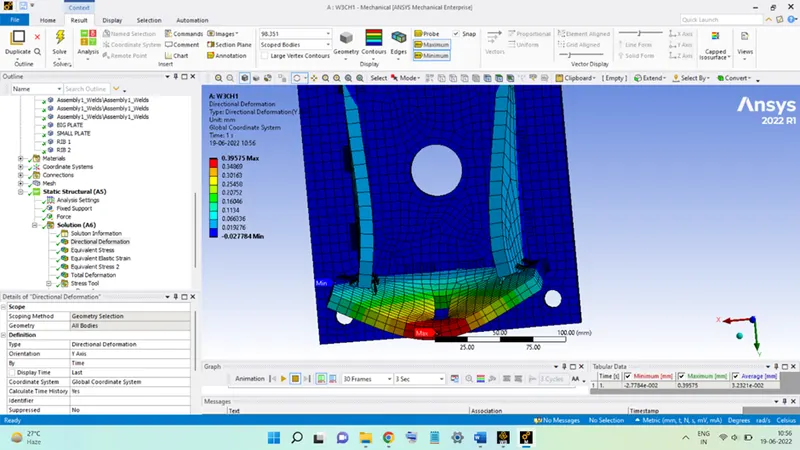
the above figure shows the behavior of the joint for the given loading condition.
The maximum deformation is seen to be occurring in the SMALL PLATE equal to 0.39575 mm.
Stress in Joint:
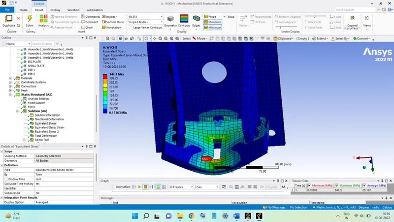
The above figure shows the stress distribution in the whole joint due to the load acting.
Again, the maximum stress is seen to be present on the SMALL PLATE equal to 347.3 MPa.
Strain in Joint:
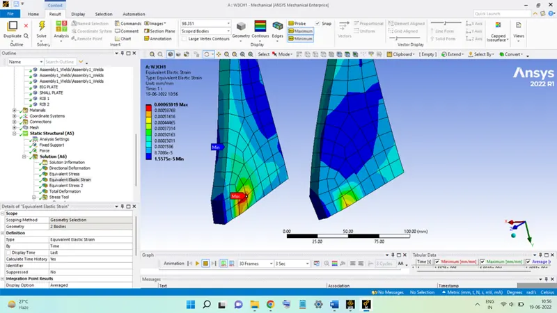
The above figure shows the strain distribution in the two RIBS of the joint due to the load acting.
The maximum strain is seen to be present in the RIB on the left equal to 6.5919 x 10⁻⁴.
Stress in Welds:
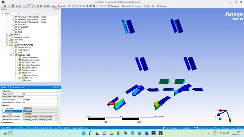
The above figure shows the stresses present in the WELDS alone due to the load acting on the joint.
The maximum stress acting is equal to 262.89 MPa.
Safety Factor in Welds:
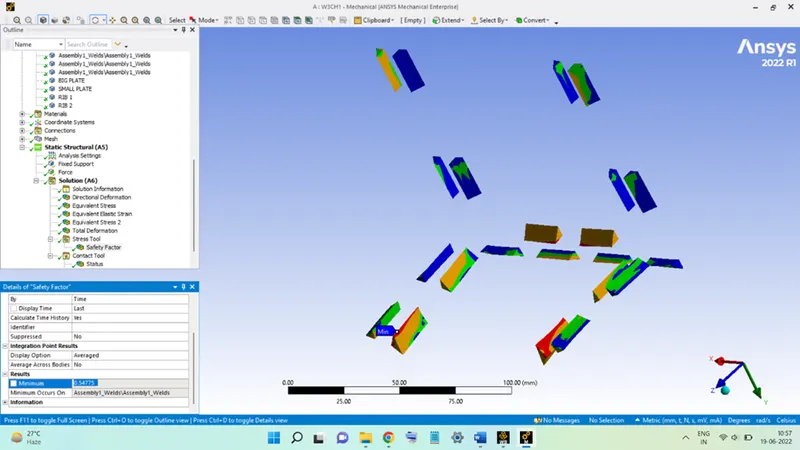
The above figures show the Safety Factor prevailing in the WELDS for the given loading condition. Most of the welds are having a decent value of the safety factor, but some of the welds are having less than the unity value of the safety factor.
The minimum value is equal to 0.54775.
Contact Status:
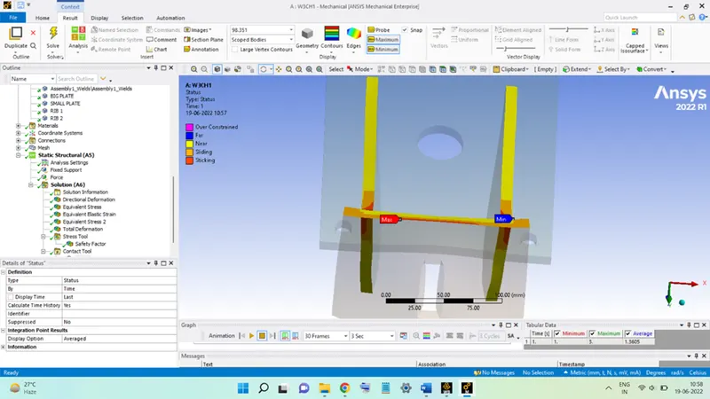
The behavior of the frictional contacts in the joint can be seen in the figures shown above. There is sticking contact in some regions, and in a few regions, the sliding and the near-contact are present.
Contact Pressure:
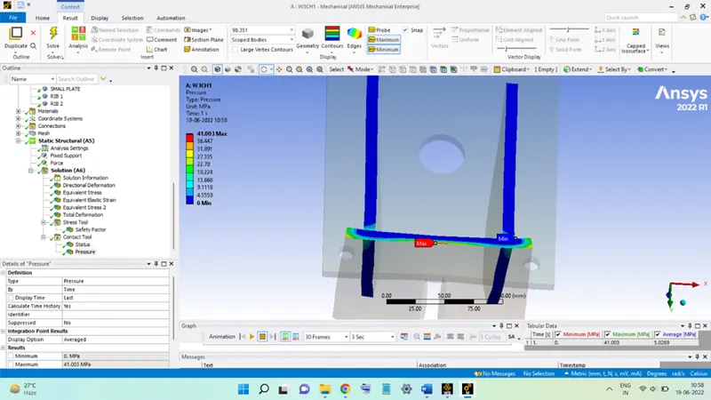
The pressure developed between the frictional contacting surfaces is shown above. Most of the contact regions are under low values of pressure, but in SMALL PLATE the pressure is seen to be reaching a maximum value of 41.003 MPa.
Comparison:
|
|
DIRECTIONAL DEFORMATION (MM) |
EQUIVALENT STRAIN |
MAX. STRESS IN WELDINGS |
SAFETY FACTOR FOR WELDINGS |
MAX. CONTACT PRESSURE (MPa) |
|
CASE 1 STAINLESS STEEL |
0.35134 |
5.091 x 10⁻⁴ |
302.42 |
0.68448 |
40.556 |
|
CASE 2 ALUMINIUM |
0.36541 |
4.916 x 10⁻⁴ |
251.74 |
1.442 |
38.755 |
|
CASE 3 BRONZE |
0.39575 |
6.5919 x 10⁻⁴ |
262.89 |
0.54775 |
41.003 |
From the above table, on comparing the different results, it can be said that for the same loading and same geometry, the:
1. Stainless steel plates with welds of stainless steel (CASE 1) exhibit the least deformation along the direction of the load and the Stainless-Steel plates have welds made of Bronze (CASE 3) is having maximum deformation.
2. The same is seen in the case of the strain developed in the plates.
3. The stress endured by the Stainless-Steel welds is maximum and is least for the Aluminium welds.
4. The least value of the Factor of Safety is seen to be for the bronze welds, followed by the Stainless-Steel welds, and then the Aluminium alloy has the highest value of the minimum factor of safety.
So, it can be said that the welds made of Bronze are most likely to fail and to prevent it the welds are to made bigger.
5. The contact pressure is also maximum for the Bronze welds.
6. So, out of the three welded joints, the Bronze welds are most adversely loaded and will be the first to fail, followed by the Stainless Steel welds.
7. The Aluminium welds can endure the load for the longest duration.