Week 3 Verification of Weld Joints
- Objective:- To simulate three different weldments for three different weld materials under a given load.
- Model Details:-Following model is given for the simulation,
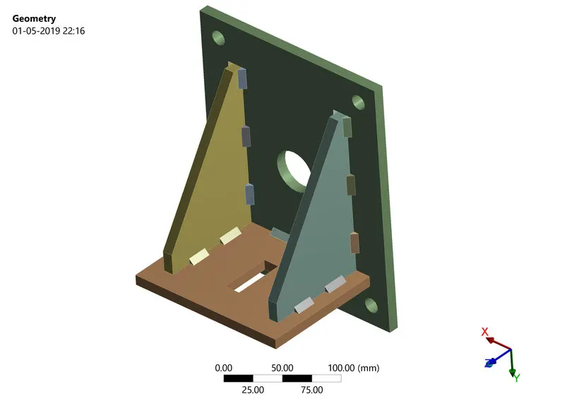
In the geometry we can see that, a vertical and a horizontal plate is welded together along with two ribs. For the meshing part, as the load is applied on the horizontal plate on the rectangular cut in it, we reduce the mesh size on that plate. After refining the mesh to maximum extent possible, we arrive at mesh as shown below.
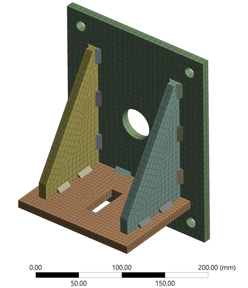
Here, I have applied 'Body Sizing' to Vertical plate (with circular hole) and the two ribs with 7.5 mm element size. And another body sizing to Horizontal plate with 5 mm element size.
Mesh Details:
Number of elements (Hex-2O):- 5186
Number of nodes:- 31863
Avg. element quality:- 0.8798
Except the 5 contacts between the 'big plate', 'small plate' and two ribs, all other contacts are kept as 'bonded'. The remaining 5 contacts are changed to 'frictional' with friction coefficient as 0.2.
The material for the weldments is to be changed for the simulation, and following three cases are to be considered,
Case-1:- Stainless Steel for all the geometries. For Stainless Steel material, its properties are,
Young's Modulus = 193 GPa
Yield Strength = 207 MPa
and UTS = 586 MPa
Case-2:- Same as case-1, except, weldments are of material Aluminium Alloy (high strength, wrought). For this, properties are,
Young's Modulus = 73.8 GPa
Yield Strength = 363 MPa
and UTS = 449 MPa
Case-3:- Plates are of SS, ribs are of copper and weldments are of bronze, cast. For copper material, properties are,
Young's Modulus = 110 GPa
Yield Strength = 280 MPa
and UTS = 430 MPa
and for bronze material,
Young's Modulus = 80 GPa
Yield Strength = 144 MPa
and UTS = 267 MPa
- Loads and Constraints:-
As can be seen from the figure below, the model is fixed on the 5 circles of the vertical plate. A load of 15000N is applied on the rectangular cut surface of the horizontal plate.
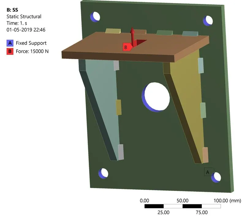
In 'Analysis Settings', Large Deflection is switched ON, and the solution is solved for single time step of 1sec.
- Results:-
For the results, we will compare the Directional Deformation, Equivalent Strain and Equivalent Stress in the three cases.
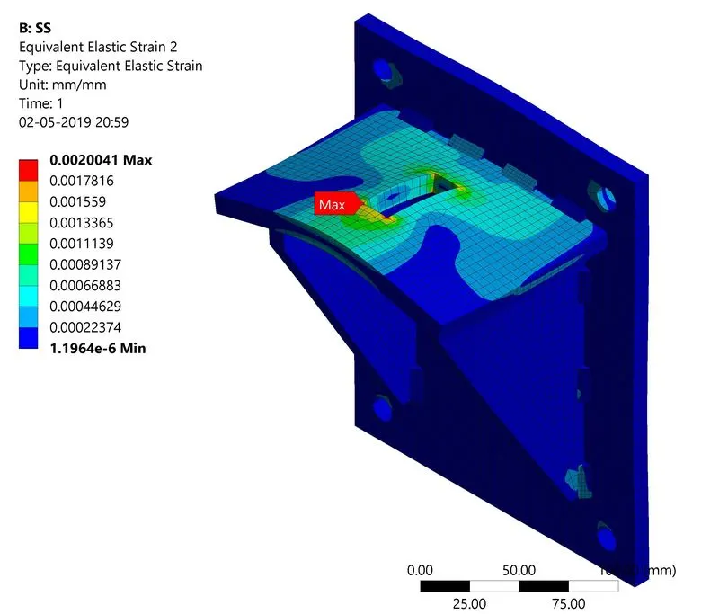
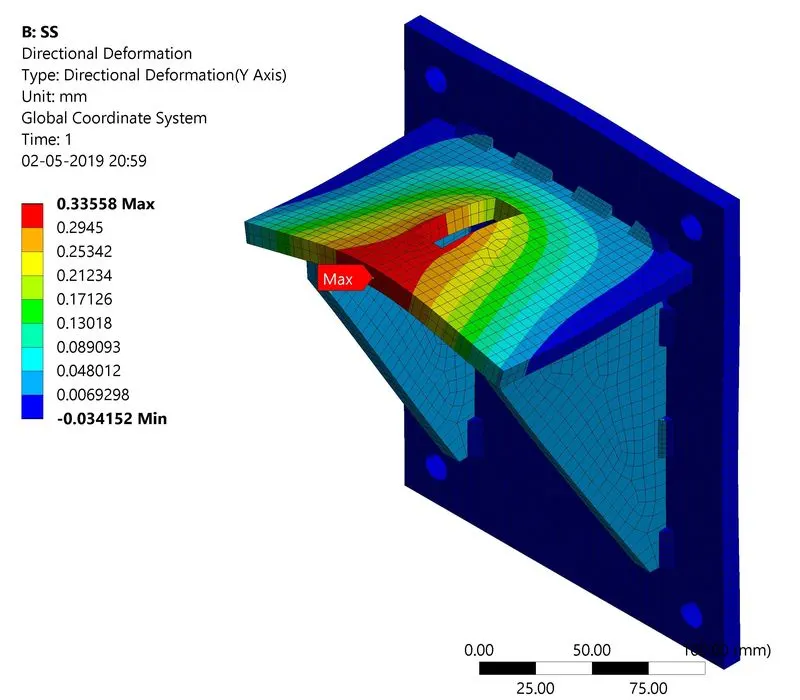
Case-1 (SS Weldments):-
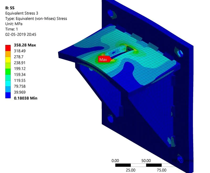
Max. Equivalent Stress = 358.28 MPa
Max. Equivalent Elastic Strain = 0.0020041 mm/mm
Directional Deformation (Y-axis) = 0.33558 mm
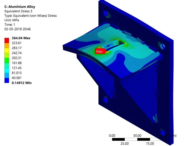
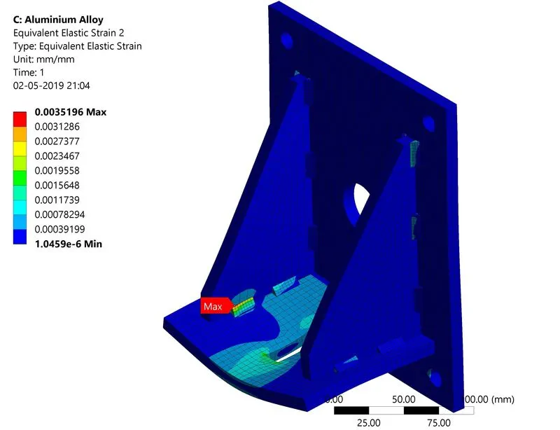
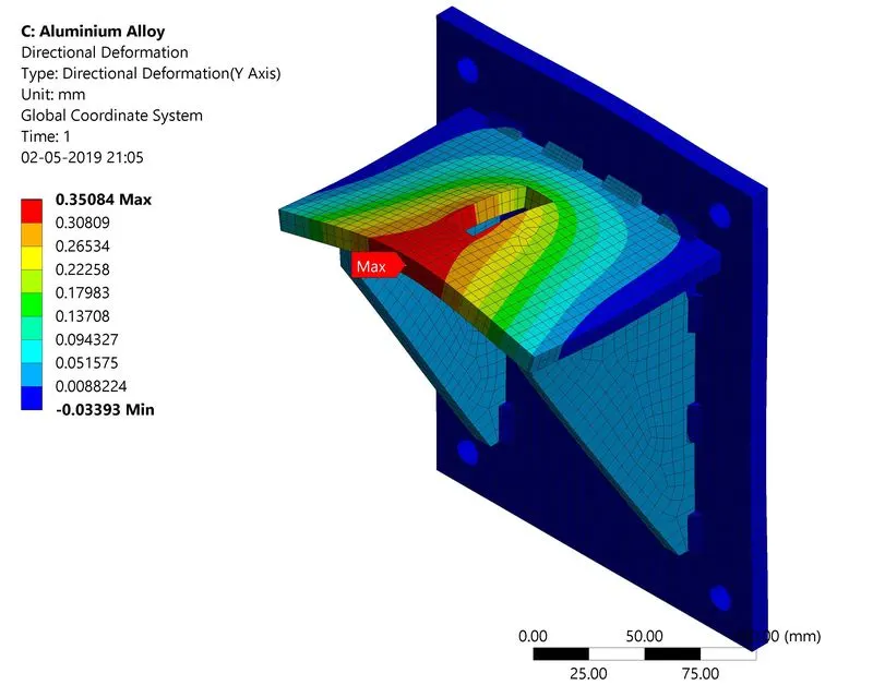
Case-2 (Aluminium Alloy Weldments):-
Max. Equivalent Stress = 364.04 MPa
Max. Equivalent Elastic Strain = 0.0035196 mm/mm
Directional Deformation (Y-axis) = 0.35084 mm
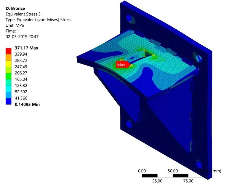
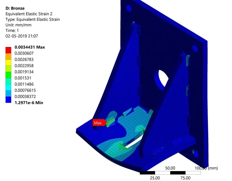
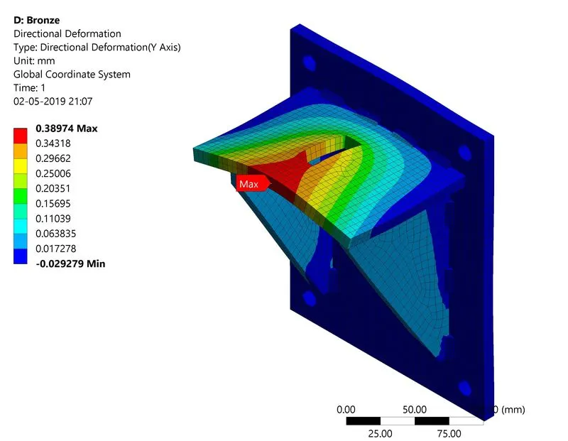
Case-3 (Bronze Weldments):-
Max. Equivalent Stress = 317.17 MPa
Max. Equivalent Elastic Strain = 0.0034431 mm/mm
Directional Deformation (Y-axis) = 0.38974 mm
- Conclusion:-
From the material data we can see that, Young's Modulus of Bronze and Aluminum Alloy is very low compared to that of SS. And so as we expect, Cas-2 and Case-3 have larger Directional Deformation than Case-1. Additionally in Case-3, ribs are made of Copper which also have lower Young's Modulus, while in Case-2 ribs are made of SS. This is evident from the images below, which compares the Directional Deformation of Ribs along for the 3 cases. Case-1 and 2 have almost same Directional Deformation whereas due to copper ribs, Directional Deformation is much higher in Case-3.
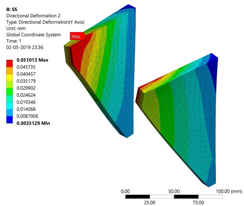
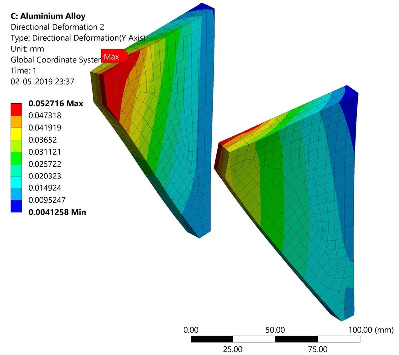
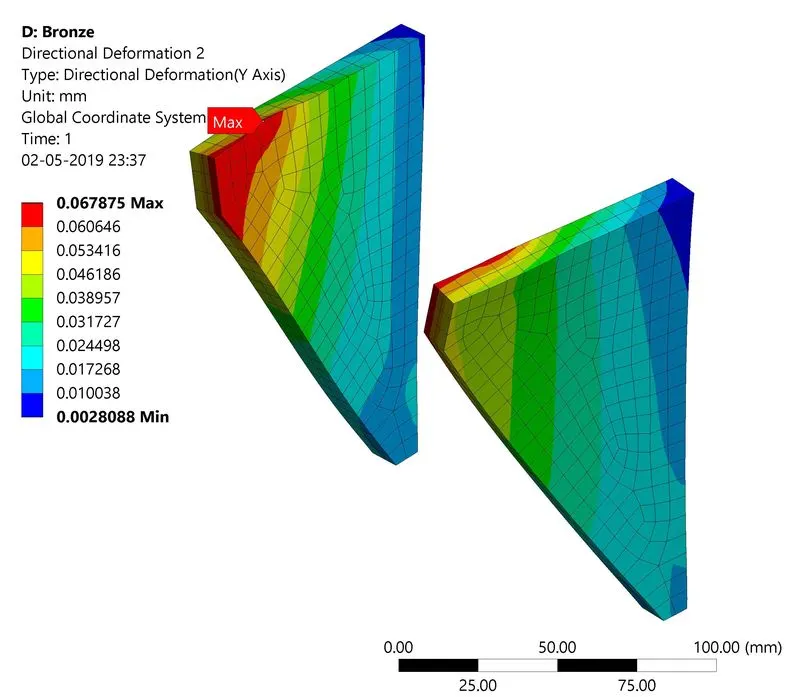
Also the Equivalent Elastic Strain is higher for Case-2 and 3 than for Case-1, this is also attributed to the lowest Young's Modulus values of Aluminium Alloy, Bronze and Copper. For Case-1 as the material is same for all the geometries, its max. value is observed at sharp corner of the rectangular cut, where external load is applied, In Case-2 and 3 however, as the weldments material is easily deformable compared to SS (due to lower Young's Modulus value), max. Equivalent Elastic Strain is observed in weldments.
The Equivalent Stress magnitude in the images above shows stress for all the geometries with increases from Case-1 to Case-3, and in all the cases it is observed at the sharp corner of rectangular cut where external load is applied, the Equivalent Stress is maximum. However, this stress is high, mainly due to sharp edge, and its variation for the three cases is less than 4%. This stress is expected to be similar, since we are not changing the Plate material, also we can see that the equivalent elastic strain is same for all the cases at this maxima point (using probe). What we should focus on is the Max. Equivalent Stress developed in the weldments shown in the figures below,
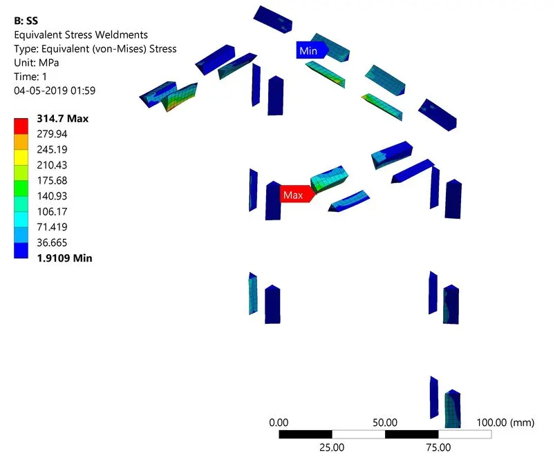
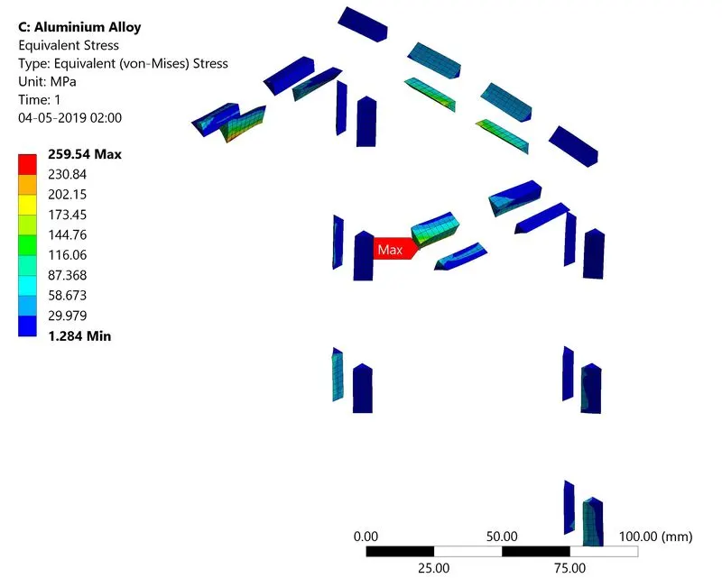
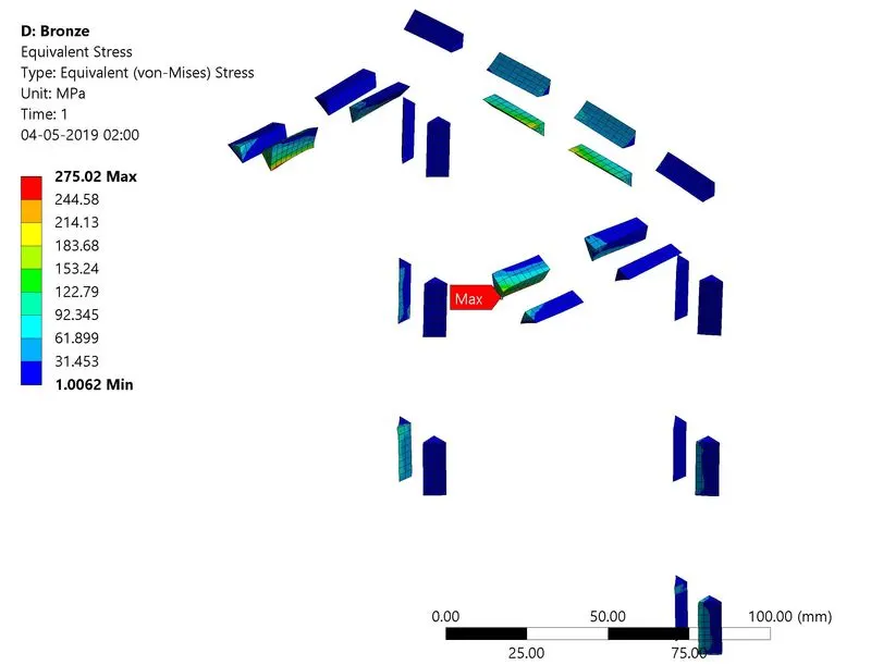
So from the images above showing Equivalent Stress for weldments only, we can see that the max. stress point is same for all the cases. It is the point where the vertical shear and vertical components of bending stress add up. And this stress is highest for the SS weldments, while it is lowest for the Aluminium Alloy weldments.
We now see the Safety Factor images for the weldments only, and we can see from the images below, Aluminum Alloy has the highest min. safety factor.
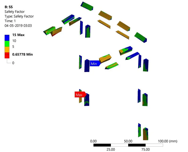
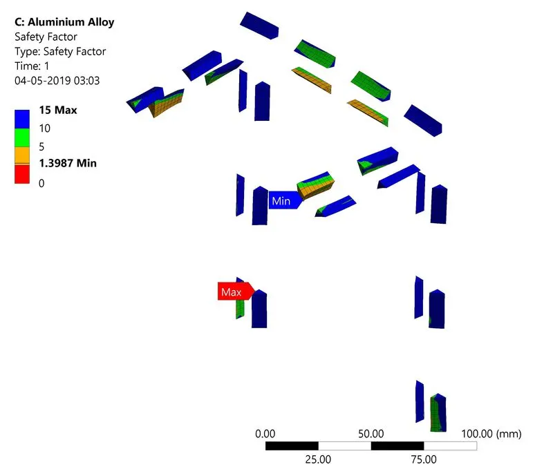
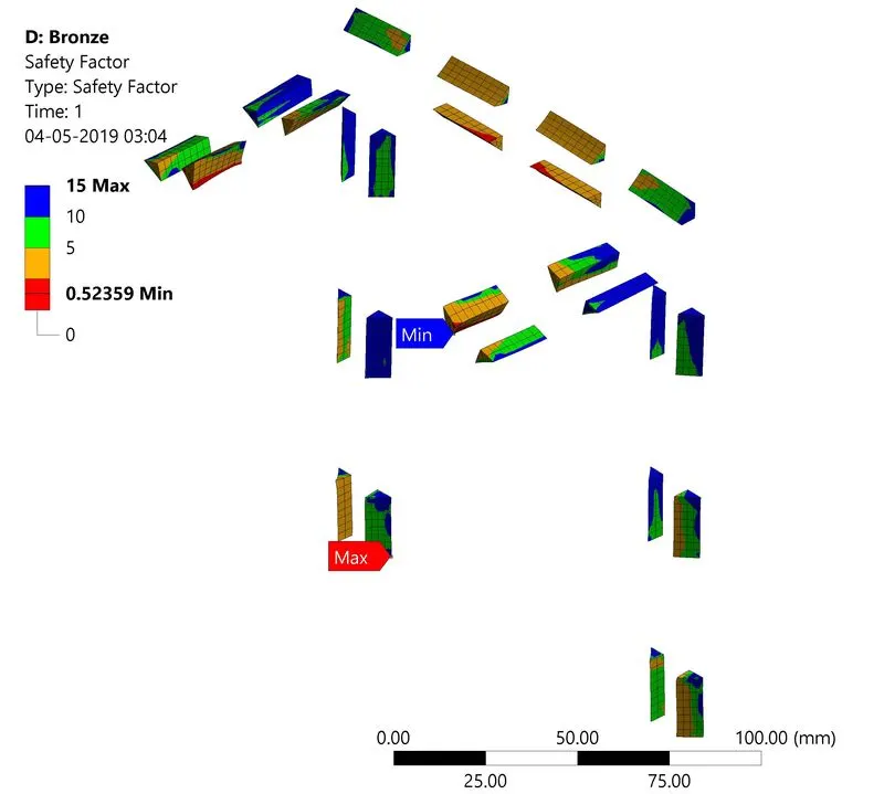
Safety factor is the ratio of actual stress to limiting value of stress (like Yield stress or UTS). For Aluminum Alloy, the Equivalent Stress generated is lowest and the Yield Strength is highest. So this justifies the high value of safety factor (almost twice that of SS). We can notice that, even though SS has highest Equivalent Stress among the three cases, its safety factor is better than bronze because of higher yield strength and UTS.