Week 3 Sheet metal Bending challenge
AIM: - PERFORM A STATIC STRUCTURAL ANALYSIS FOR A SHEET METAL BENDING OPERATION FOR THREE DIFFERENT SHEET METALS AND COMPARE THE RESULTS.
Objectives:
Perform the static structural analysis for the sheet metal bending operation for three different sheet metal materials:
Aluminium Alloy 1199.
Copper Alloy NL.
Magnesium Alloy NL.
Change the friction coefficient to 0.19 and perform the analysis for the Aluminium Alloy.
Refine the mesh without exceeding the academic limit and run the analysis for the Aluminium Alloy.
Start with launching Ansys Workbench, and select the Static Structural Analysis from the analysis systems.
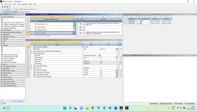
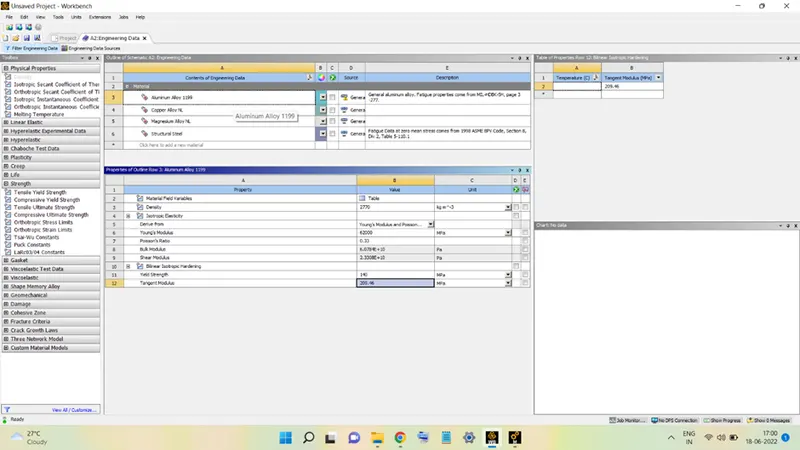
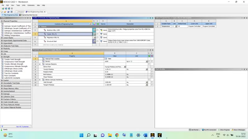
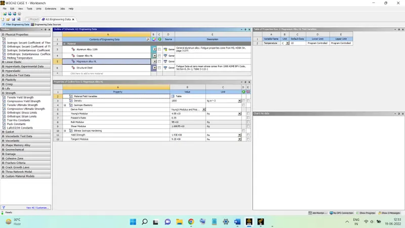
Click o the Engineering Data to add the required materials to the project environment. The properties of the respective materials used in the project are shown as follows:
Structural Steel:
Aluminium Alloy 1199:
Copper Alloy NL:
Magnesium Alloy NL:
Now import the geometry from the stored location into the project environment. Then, double-click to open it in SpaceClaim and check for any abnormalities in it.
Now, click on Model and select Edit to launch the Mechanical Module and the load geometry in the module.
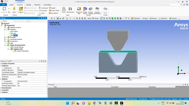
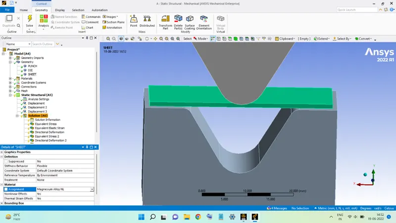
Next, expand the Geometry option and rename the parts in the geometry as shown below:
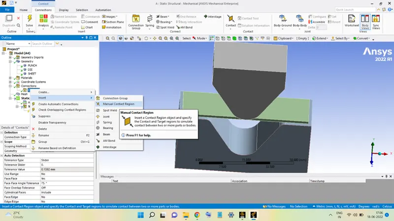
Expand the Connections option and delete all the previously present Contact regions. Now, add the new Contacts by right-clicking on Contact then going to Insert and selecting the Manual Contact region.
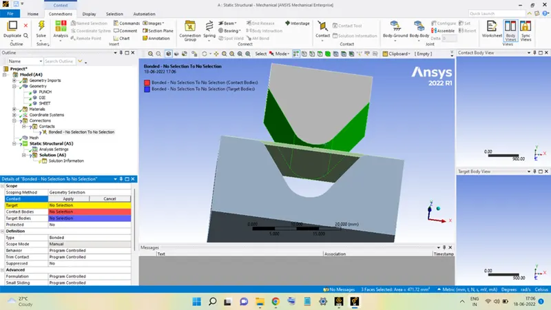
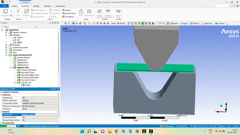
The first contact region will be between the PUNCH and the SHEET. Select the Punch surfaces as Contact and Sheet surfaces as Target.
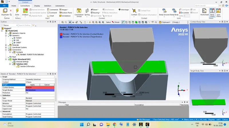
Add the second contact region between the SHEET and the DIE. The Sheet bottom surface will be the Contact and the Die surfaces will be the Targets.
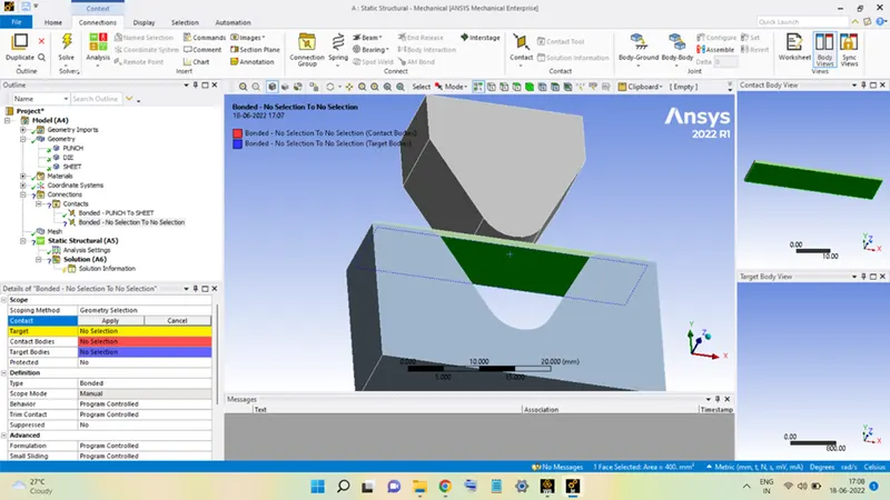
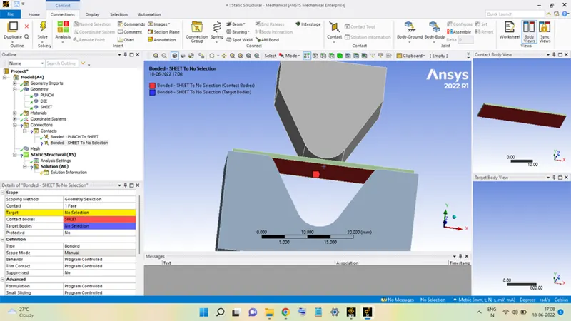
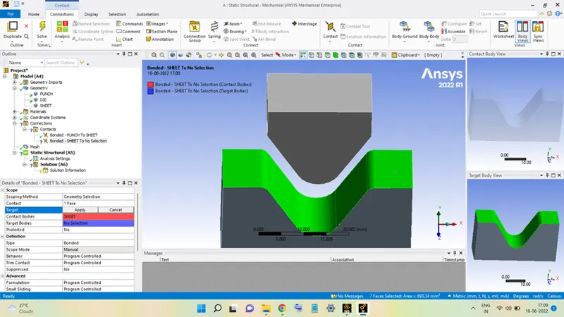
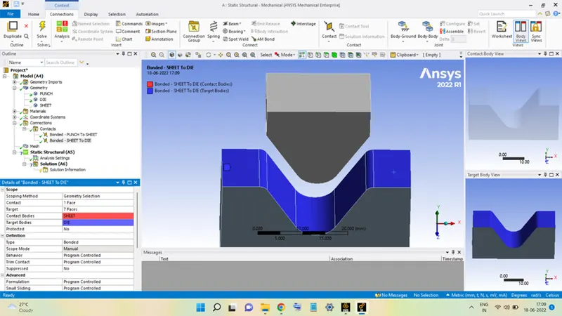
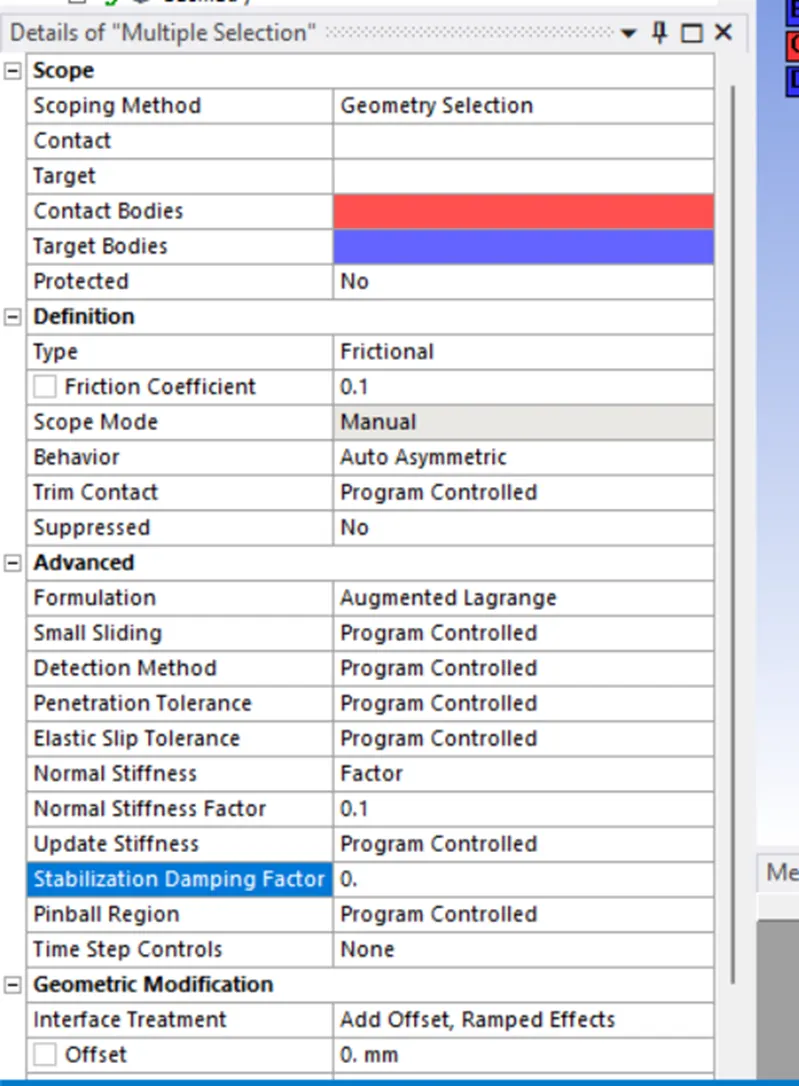
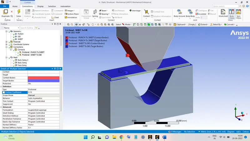
Now select both the contacts and assign the Type as Frictional and set the Friction Coefficient as 0.1.
Behaviour is set to Auto Asymmetric. The Formulation is taken as Augmented Lagrange.
Change the Normal Stiffness settings to Factor and set the value of Normal Stiffness Coefficient equal to 0.1.
Finally, set the Geometric Modification as Add Offset, Ramped Effects.
Now next is to perform the Meshing of the geometry. First, right-click on Mesh, go to Insert, and select Sizing.
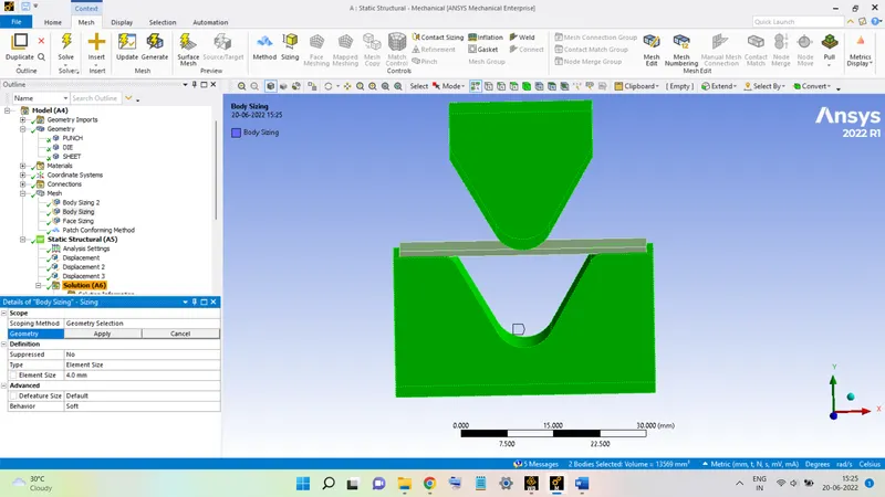
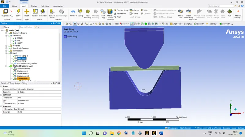
Select the PUNCH and DIE bodies, and click Apply in Geometry option. Then set the Element Size equal to 4 mm.
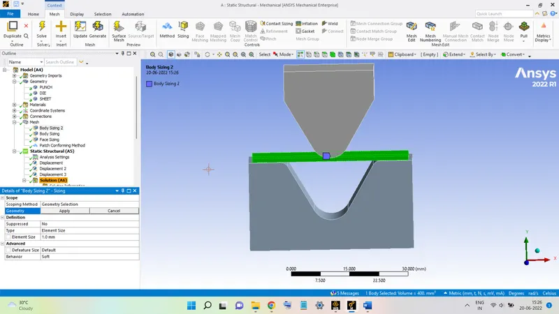
Now, again choose the Sizing option and then select the SHEET body, set the Element Size for the SHEET as 1 mm.
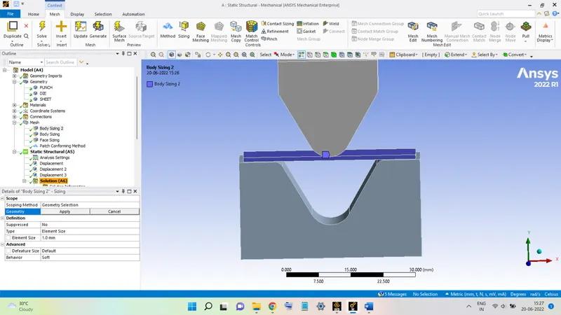
again, choose the Sizing option, and in this select the faces of the PUNCH and DIE as shown below:
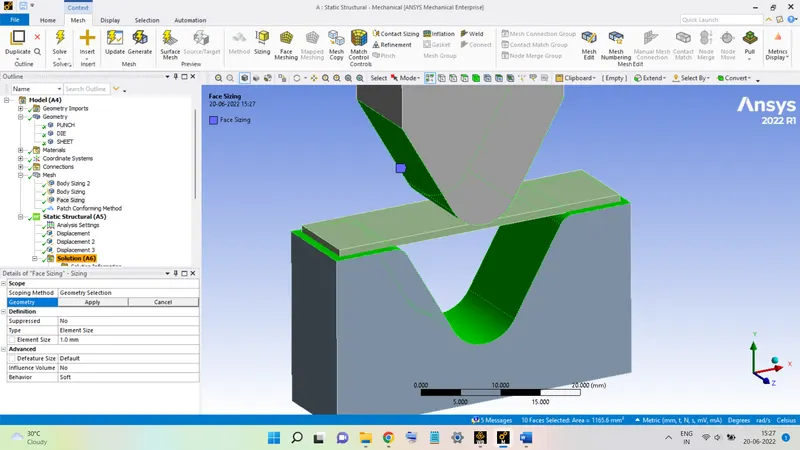
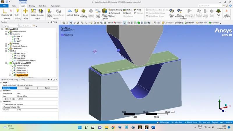
Then, right-click on Mesh go to Insert and select the Method option, select the SHEET body and change the Method settings to Tetrahedron.
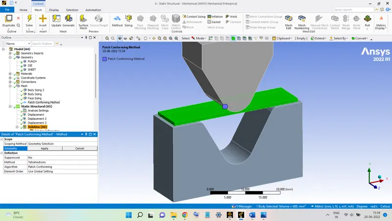
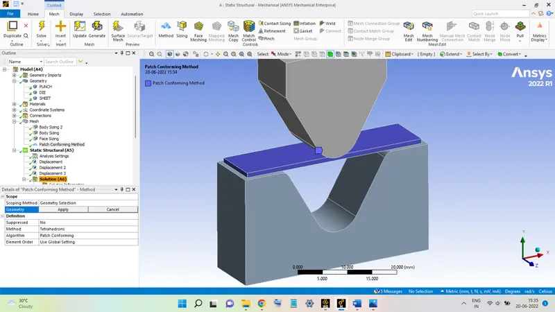
Finally, hit Apply and set the Element Size as 1 mm and then right-click and select Generate Mesh to create the mesh. The mesh generated with the number of elements and nodes is shown below:
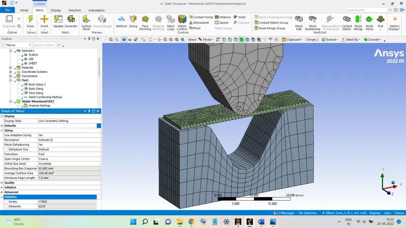
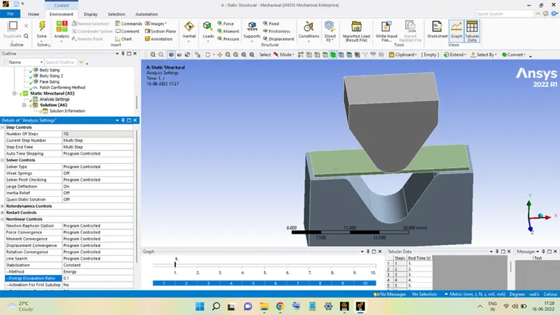
The next step is to assign the Analysis Settings to the geometry. To do so, first, change the Number of Steps to 10 and select all the steps.
Turn ON the Large deflection. In the Nonlinear Controls change Stabilization to Constant and enter the value of 0.1 for the Energy Dissipation Ratio.
Now, bodies must be assigned with respective displacement motions.
The PUNCH is given motion in negative Y-direction as shown in the figures below:
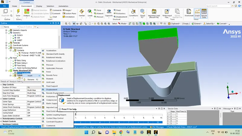
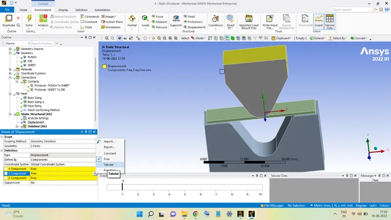
The PUNCH, first, will move down a total distance of 13.5 mm, in which it will bend the SHEET. After that, PUNCH will move away from the SHEET by a distance of 5.5 mm.
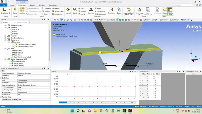
The SHEET is fixed in Z-direction and is free to move in the rest two directions.
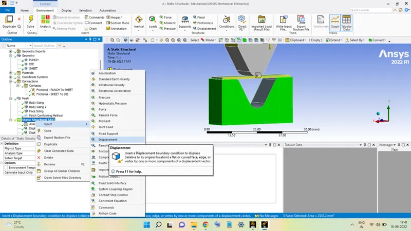
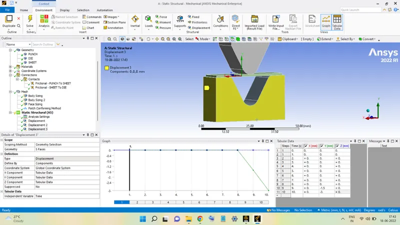
Finally, the DIE is also allowed to move in negative Y-direction only by a distance of 3 mm, that too when the PUNCH is already moved away from the SHEET after performing the bending operation.
after supplying all necessary settings the model will look like this:
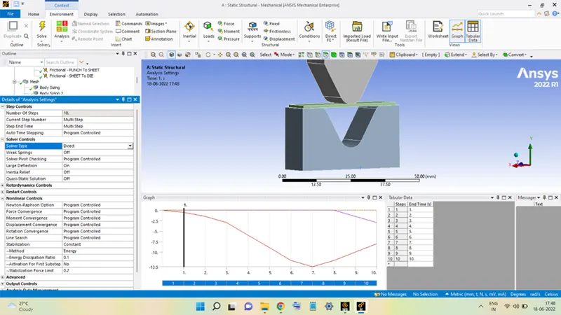
With this the geometry is ready for the analysis, click on Solve to start the analysis.
RESULTS:
CASE 1: SHEET METAL IS MADE OF ALLUMINIUM ALLOY 1199:
Stress:
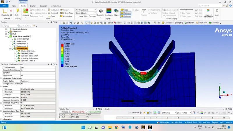
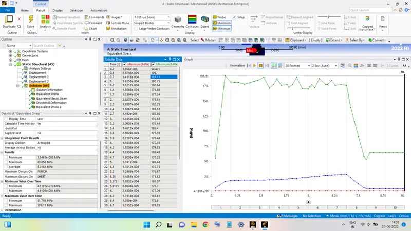
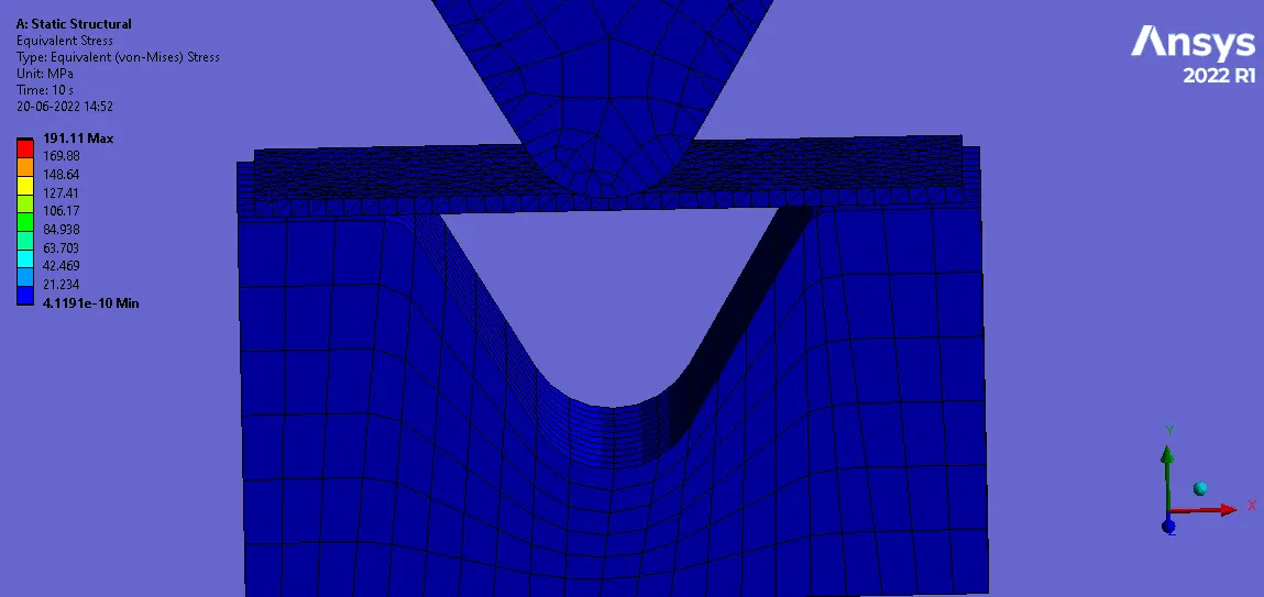
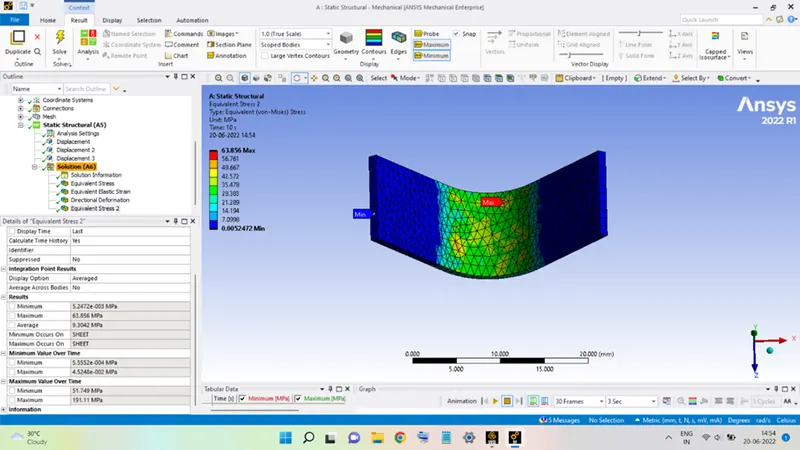
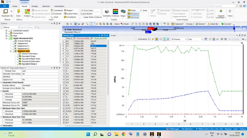
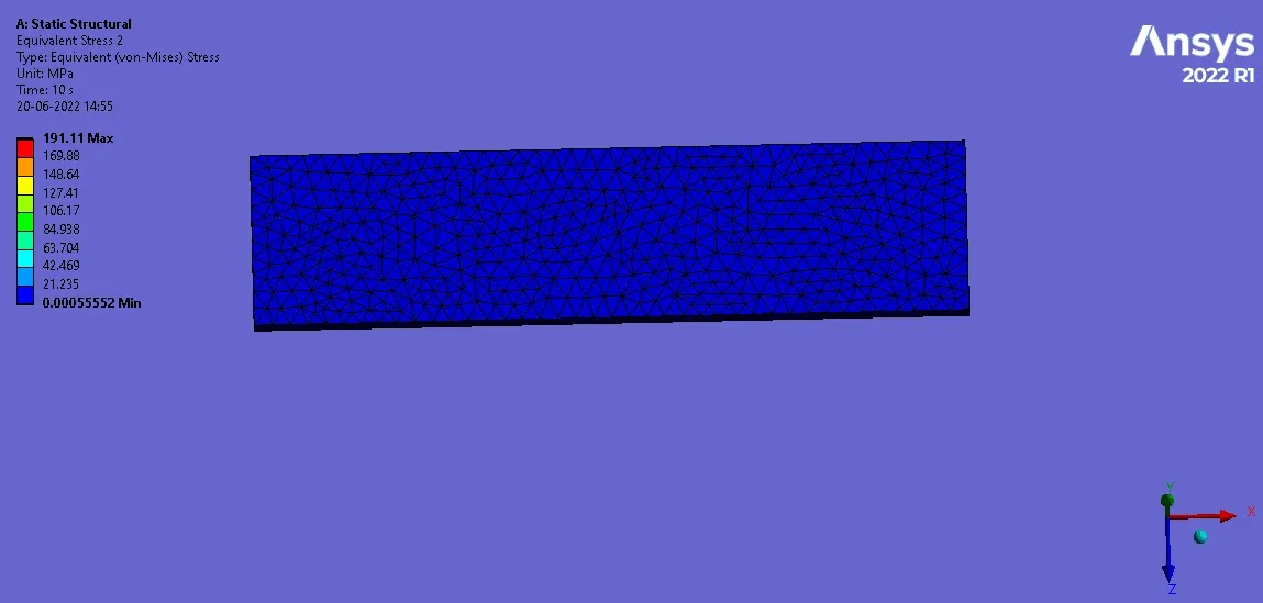
The maximum stress developed, as seen in the figure, is equal to 191.11 MPa.
Strain:
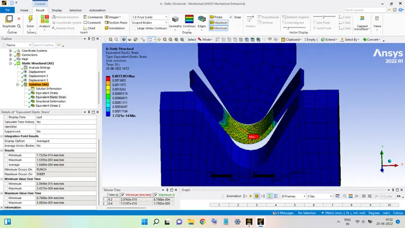
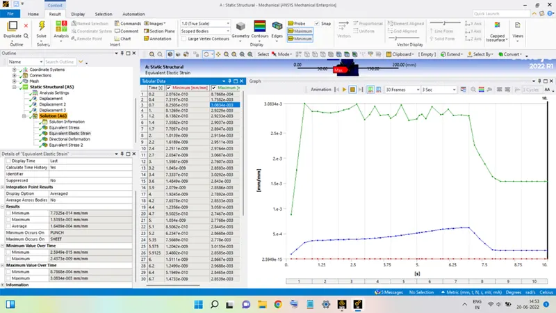
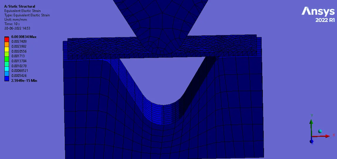
The variation of the Von-Mises strains developed throughout the bending action in the setup can be seen above. The maximum value reached is 3.0834 x 10⁻³.
Deformation in Y-Direction:
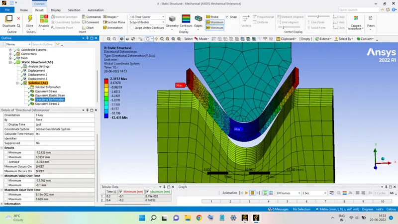
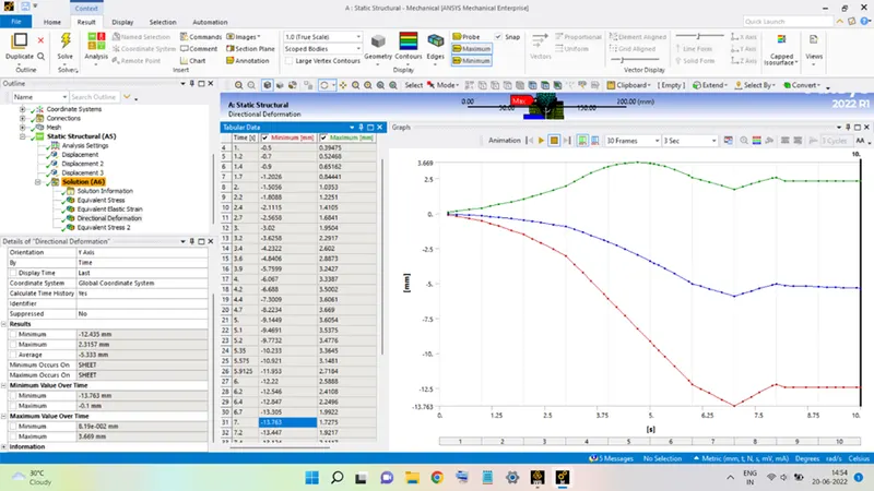
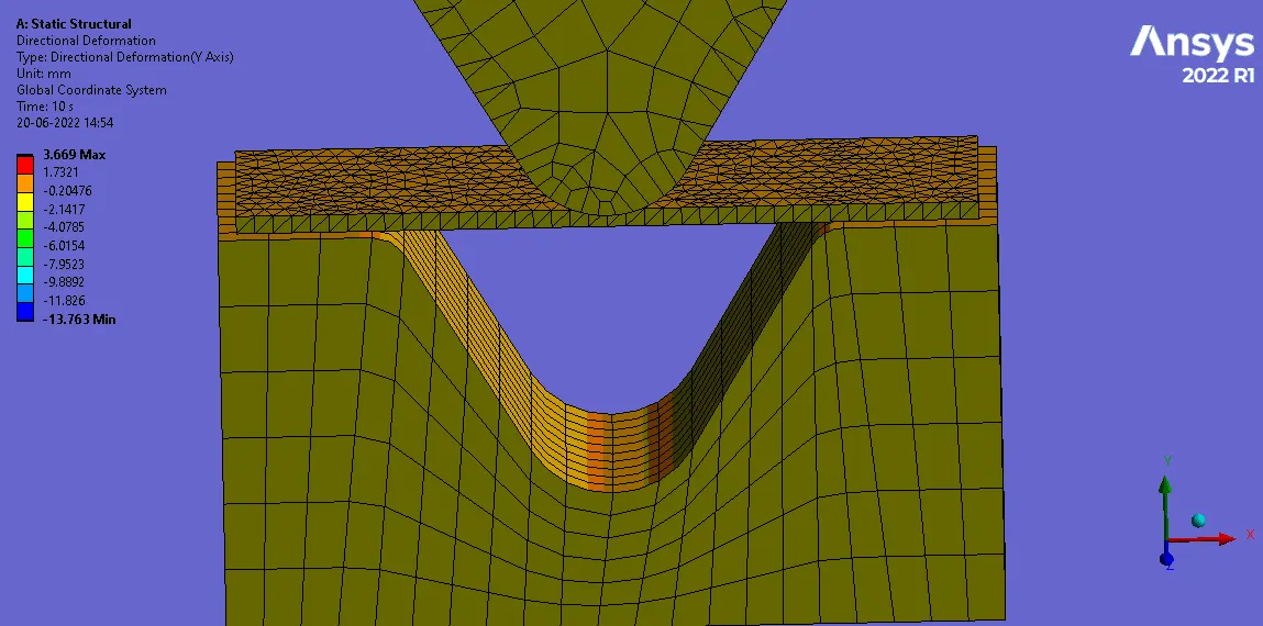
The deformation along the Y-direction is shown in the figures above.
Stress in SHEET:
The below figures show the distribution and variation of the stress in the Sheet metal during the bending is carried out. The maximum value reached during the process is seen to be 191.11 MPa.
Contact Status between Punch and Sheet:
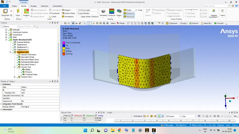
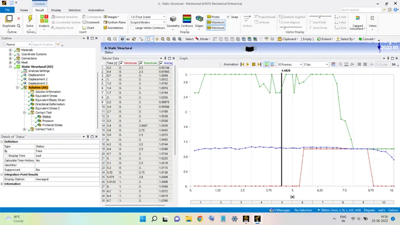
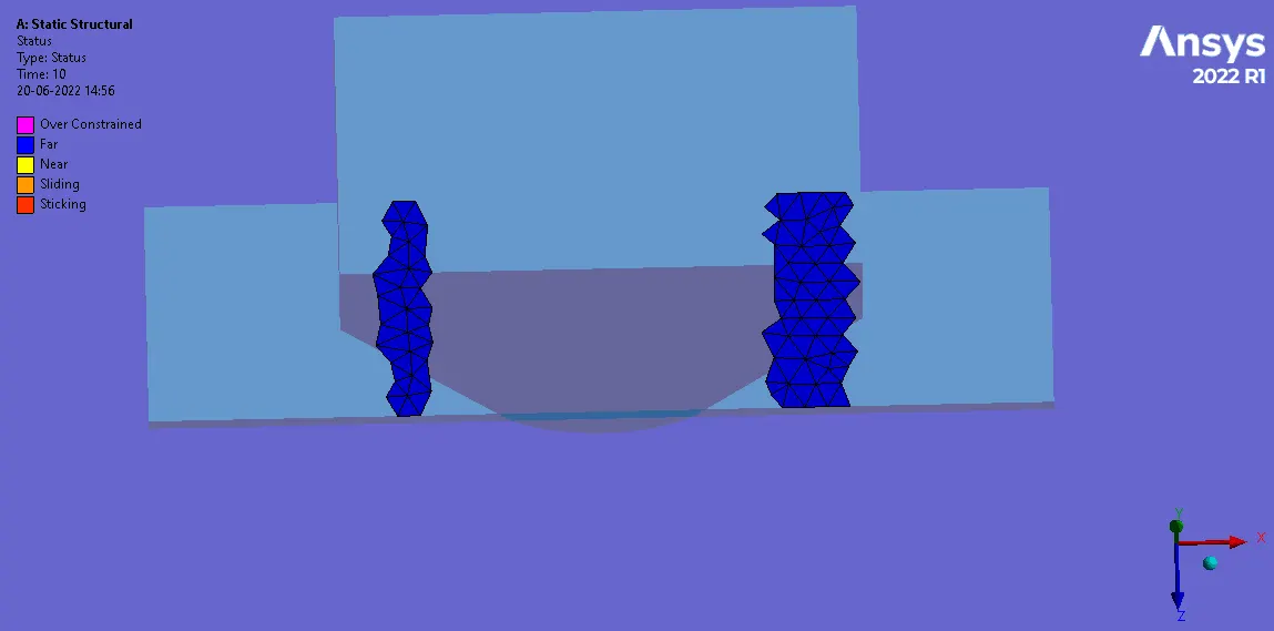
The behaviour of the contacting surfaces of the Sheet and the Die during the bending action can be seen in the figures below:
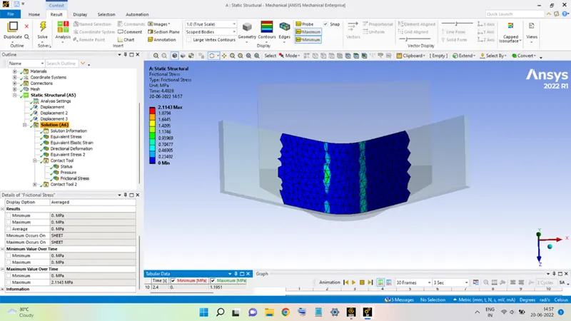
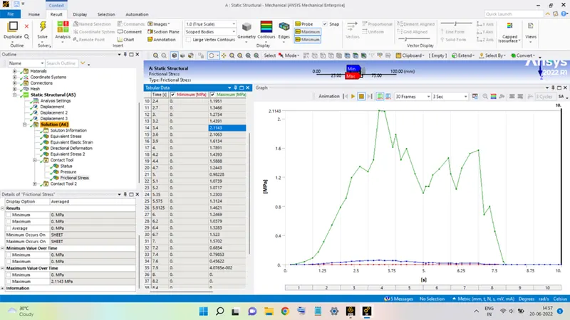
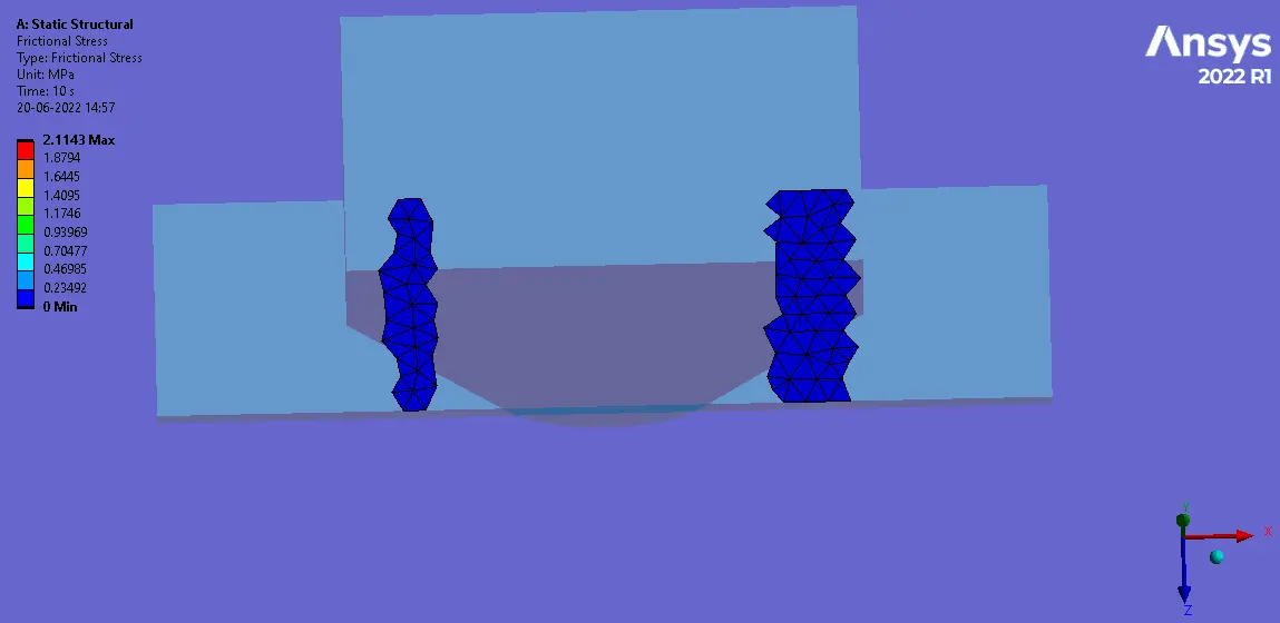
Frictional Stress between Punch and Sheet:
The frictional stresses present between the Sheet and the Die are shown below, it reaches a maximum value of 2.1143 MPa during the bending operation.
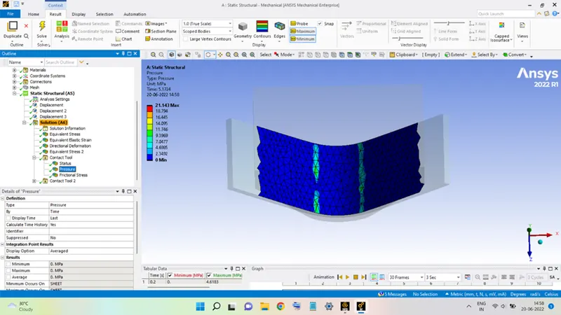
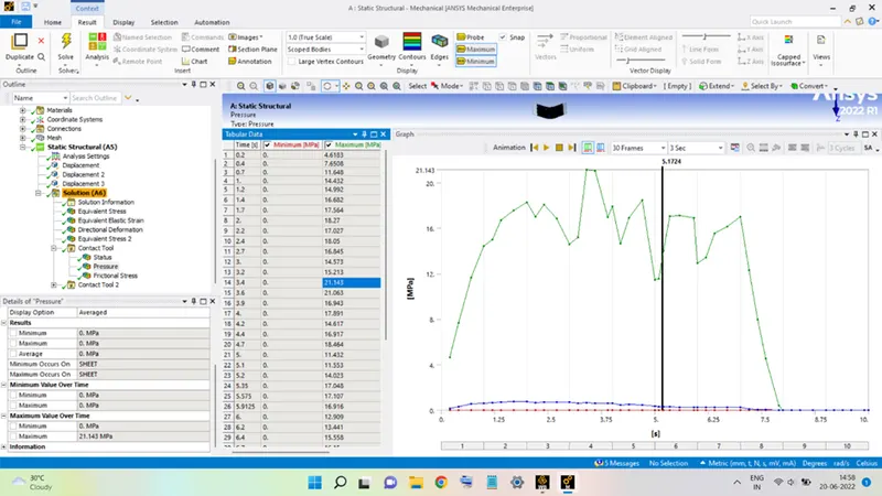
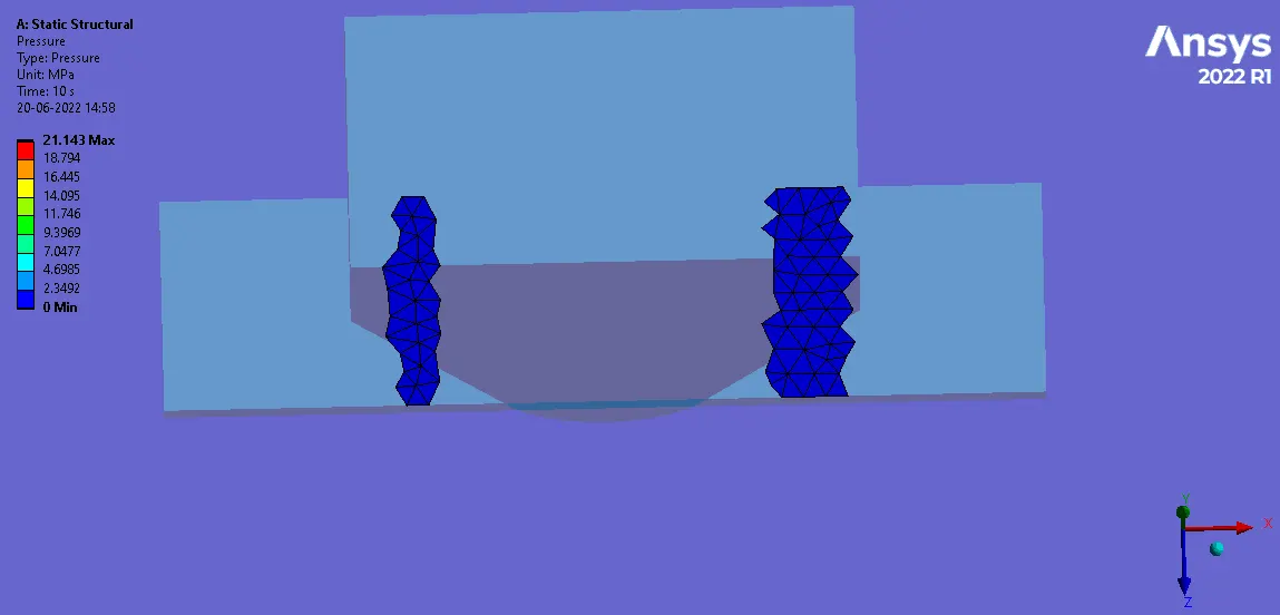
Pressure between Punch and Sheet:
The variation of the pressure between the sheet and the die contacting surfaces is seen in the figures below. This pressure attains a maximum value of 21.143 MPa.
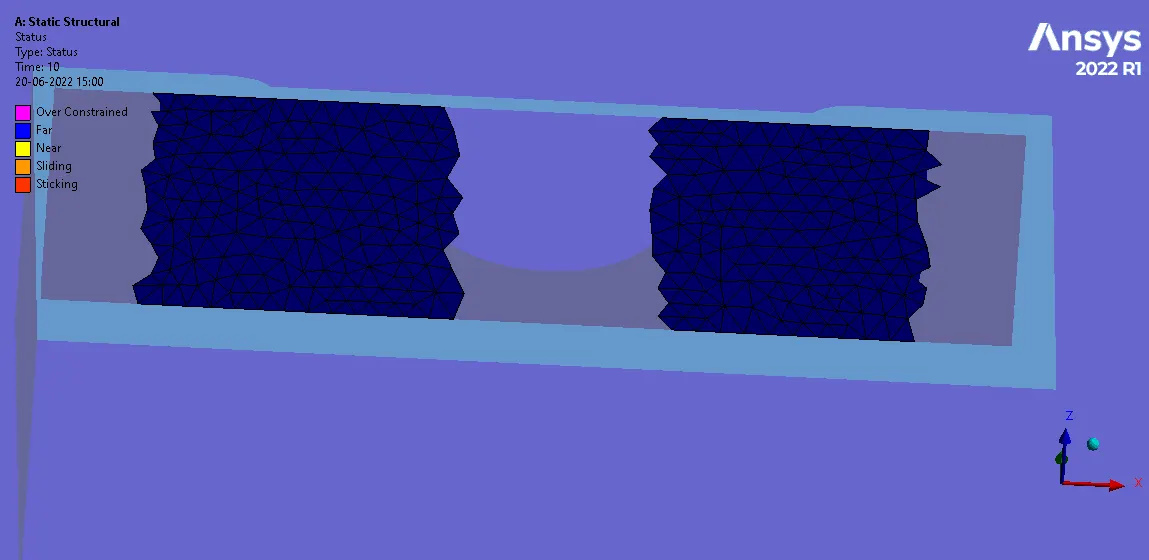
Contact Status between Die and Sheet:
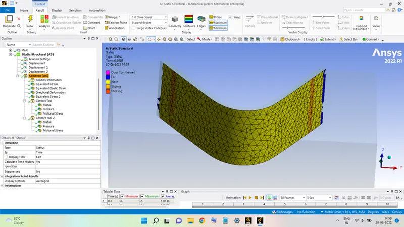
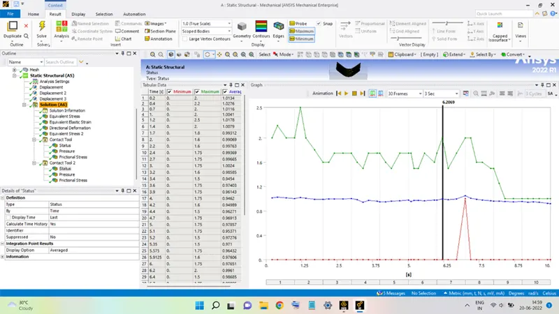
The behaviour of the contacting surfaces of the Sheet and the Die during the bending action can be seen in the figures below:
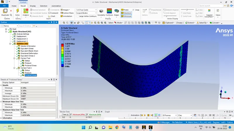
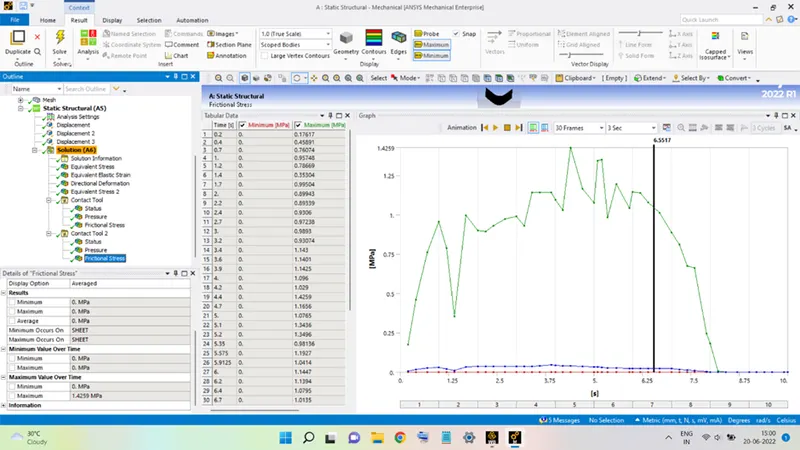
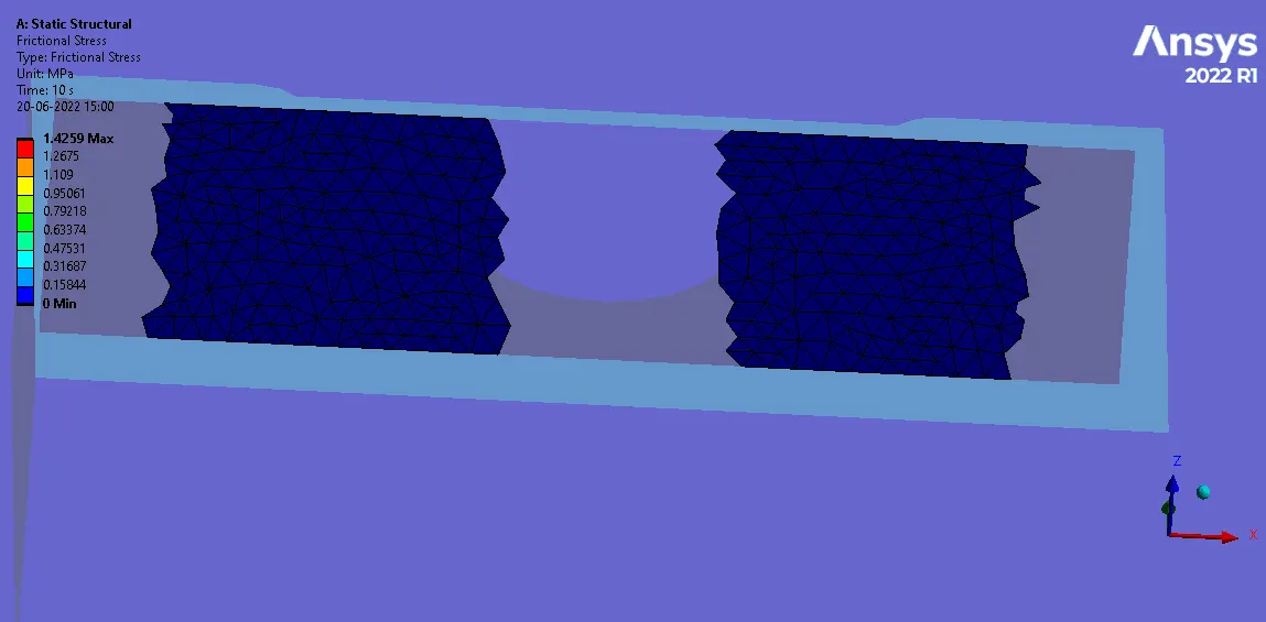
Frictional Stress between Die and Sheet:
The frictional stresses present between the Sheet and the Die are shown below, it reaches a maximum value of 1.4259 MPa during the bending operation.
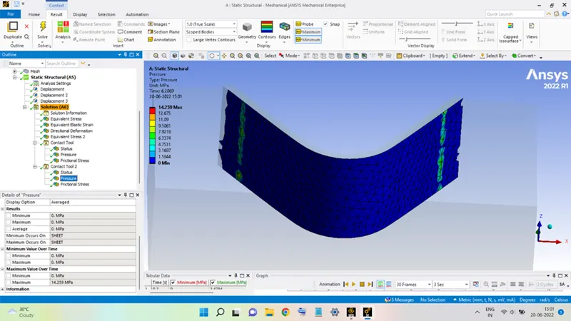
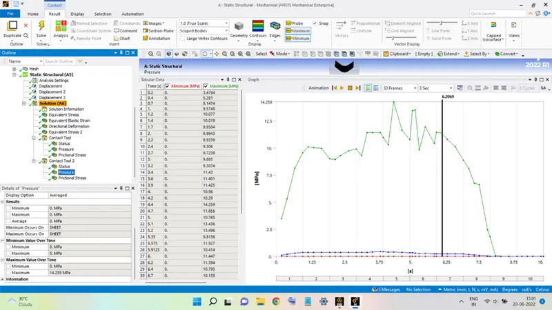
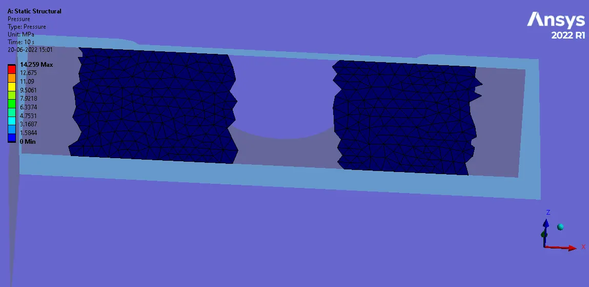
Pressure between Die and Sheet:
The variation of the pressure between the sheet and the die contacting surfaces is seen in the figures below. This pressure attains a maximum value of 14.259 MPa.
CASE 2: SHEET METAL IS MADE OF COPPER ALLOY NL:
Stress:
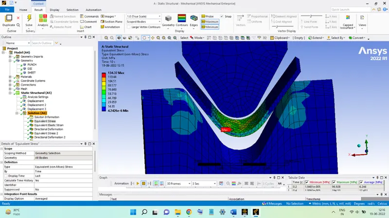
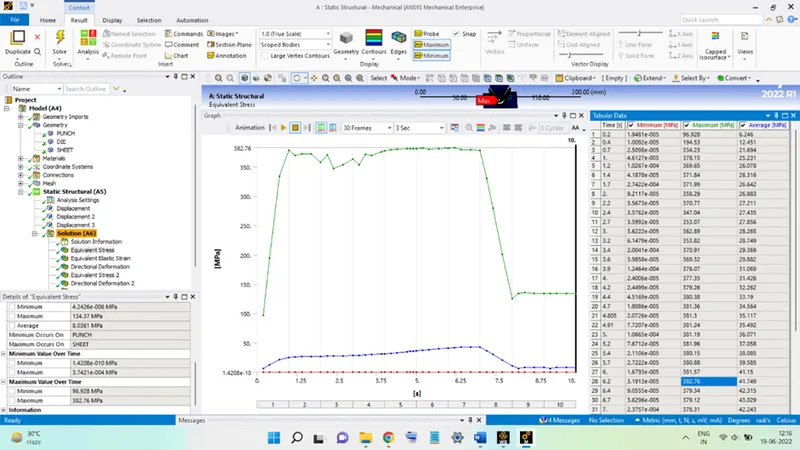
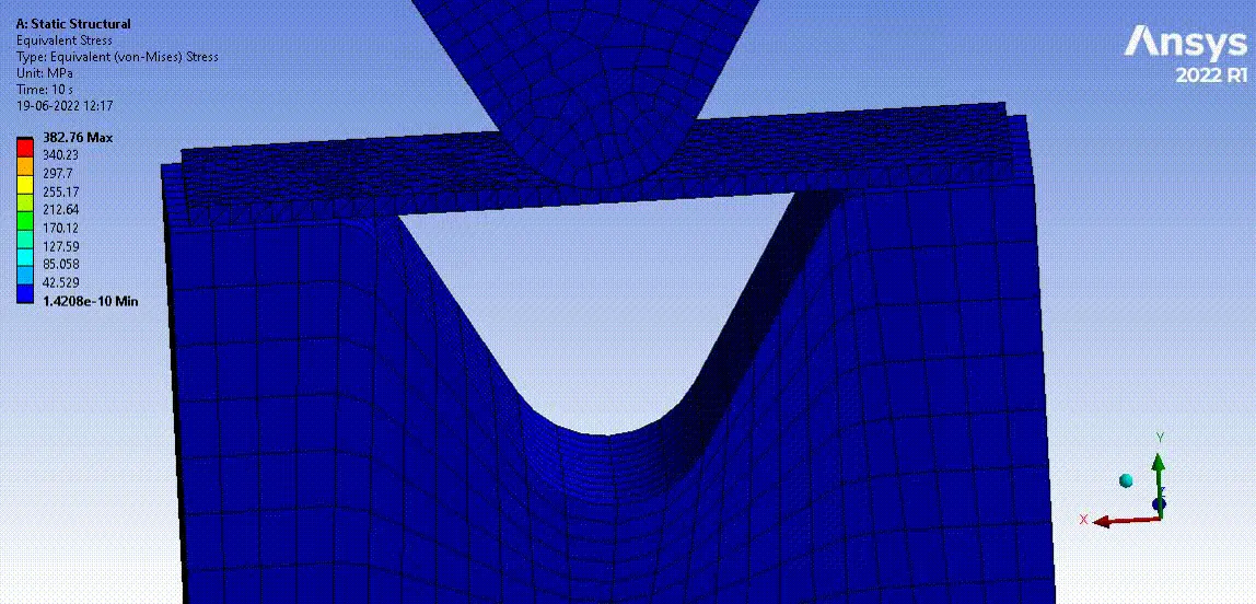
The maximum stress developed, as seen in the figure, is equal to 382.76 MPa.
Strain:
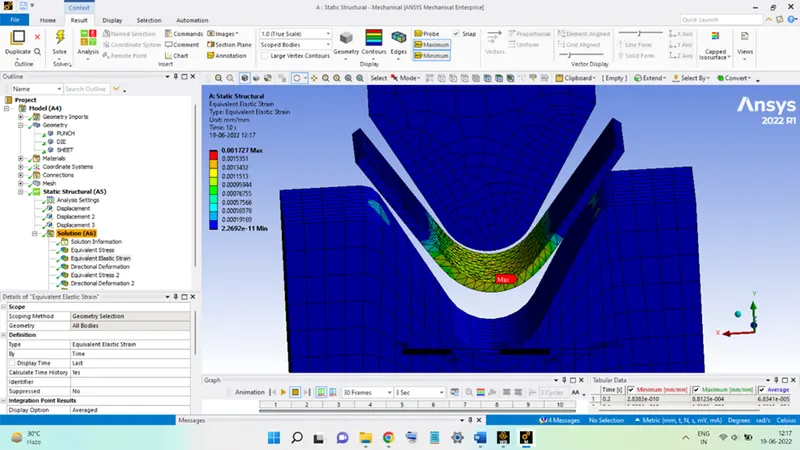
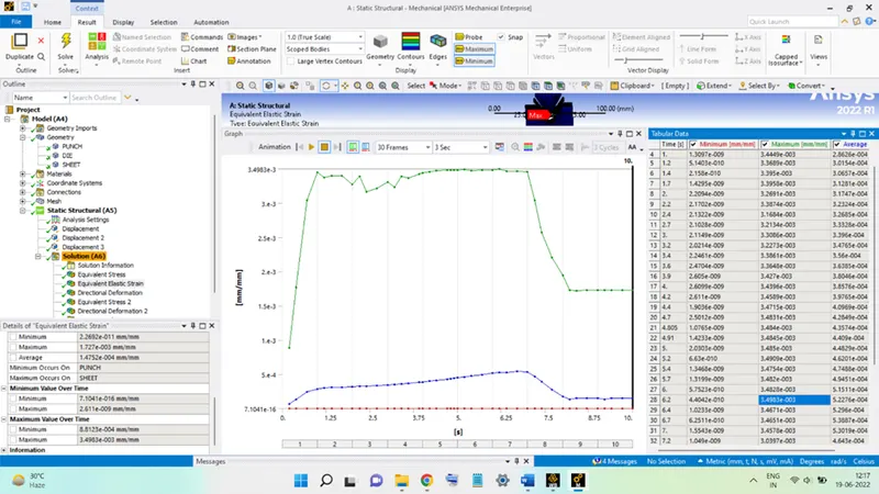
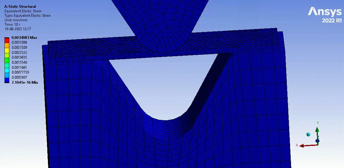
The variation of the Von-Mises strains developed throughout the bending action in the setup can be seen above. The maximum value reached is 3.4983 x 10⁻³.
Deformation in Y-Direction:
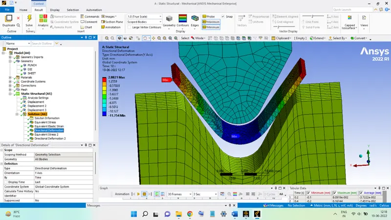
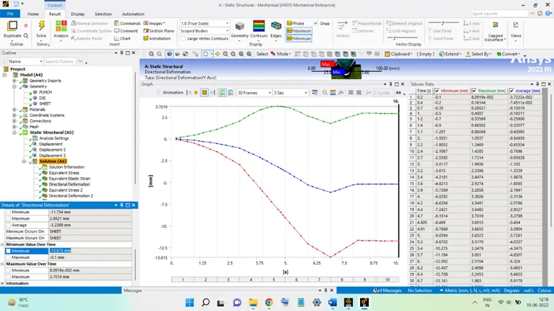
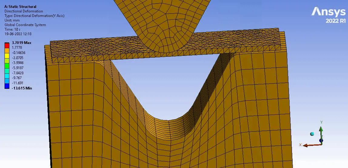
The deformation along the Y-direction is shown in the figures above.
Stress in Sheet:
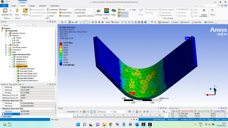
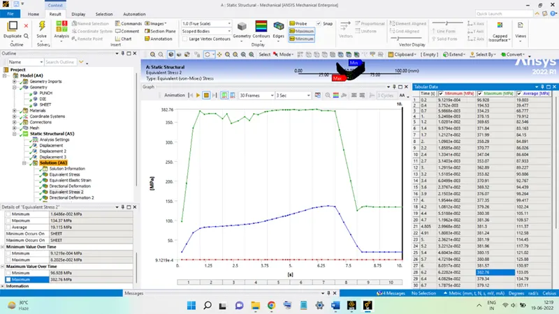
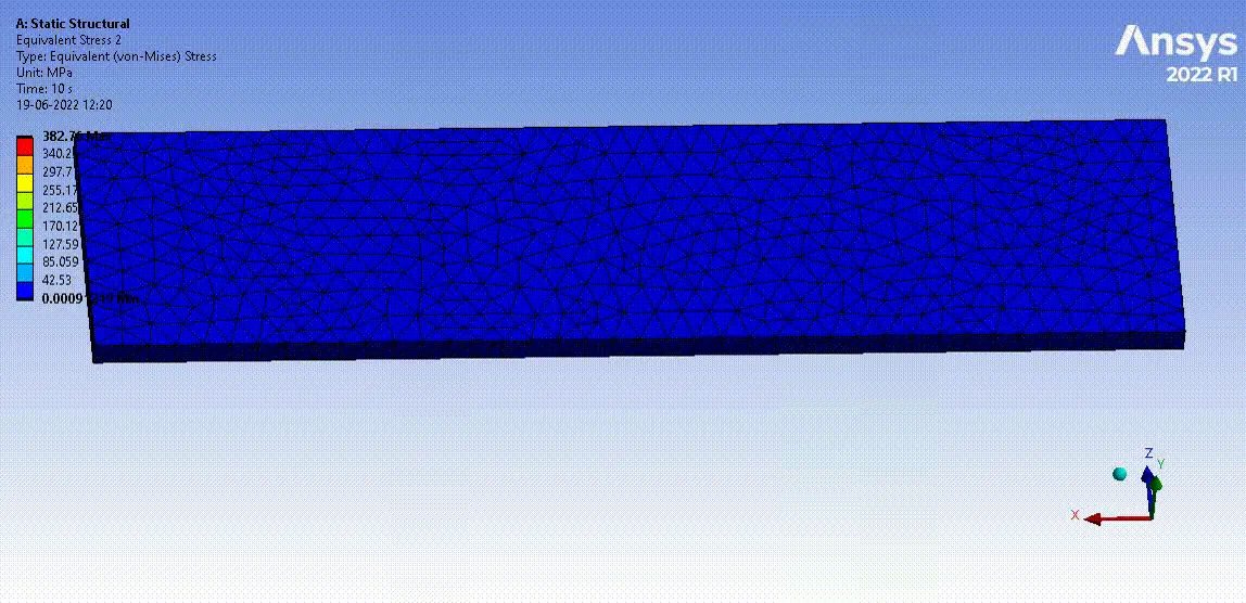
The above figures show the distribution and variation of the stress in the Sheet metal during the bending is carried out. The maximum value reached during the process is seen to be 382.76 MPa.
Contact Status between Punch and Sheet:
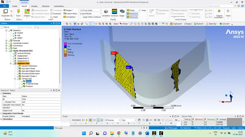
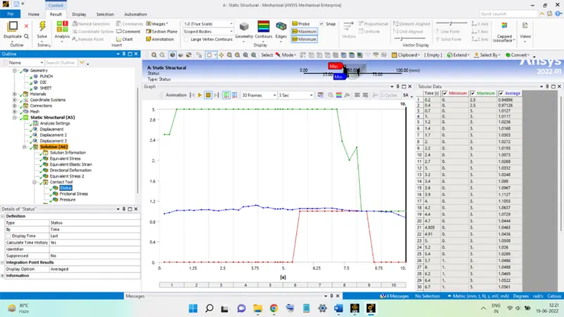
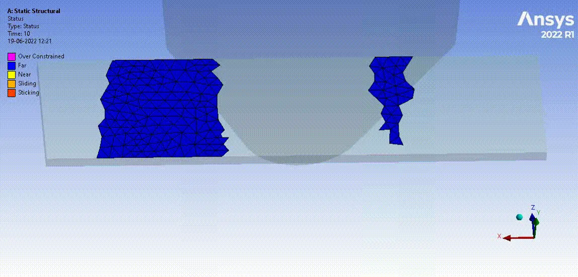
The behaviour of the contacting surfaces of the Sheet and the Die during the bending action can be seen in the above figures.
Frictional Stress between Punch and Sheet:
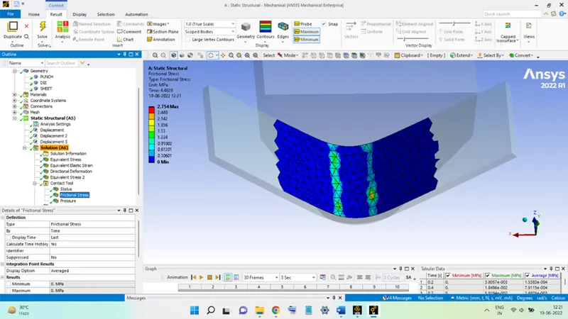
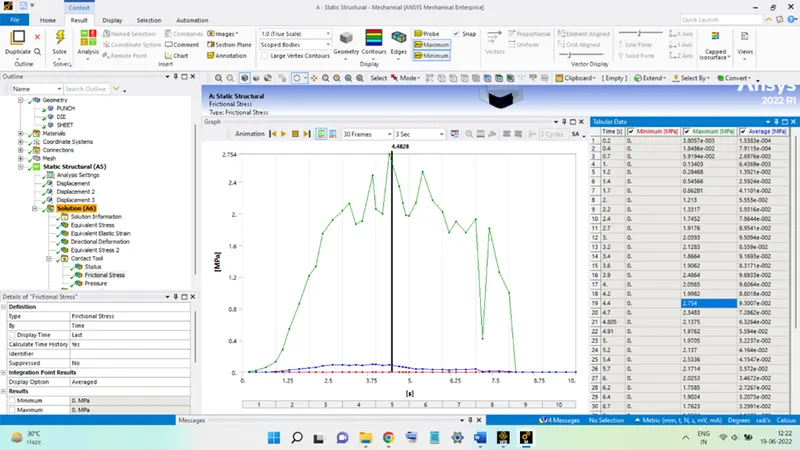
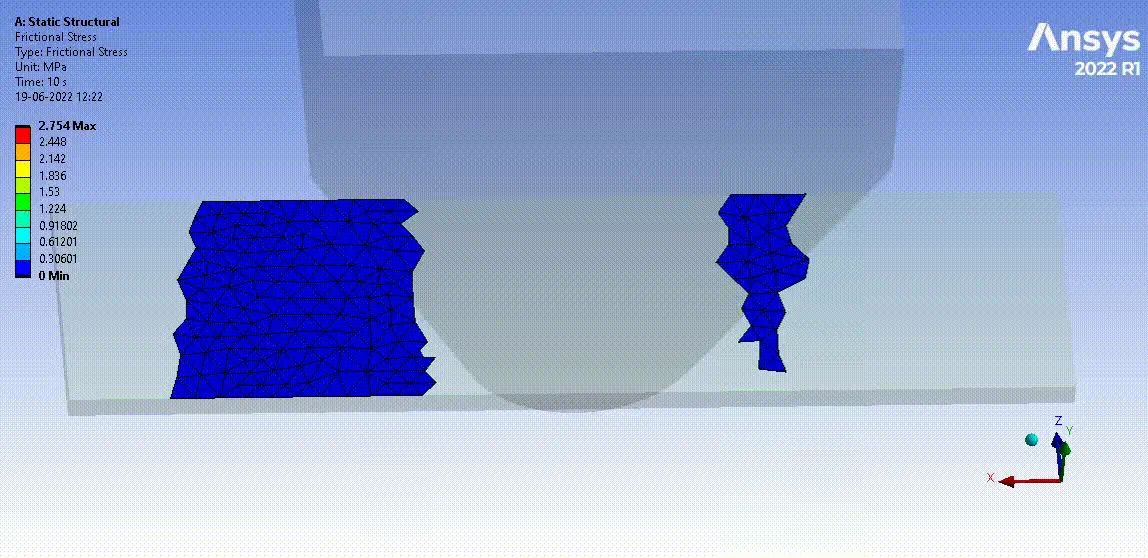
The frictional stresses present between the Sheet and the Die are shown in the above figures, it reaches a maximum value of 2.754 MPa during the bending operation.
Pressure between Punch and Sheet:
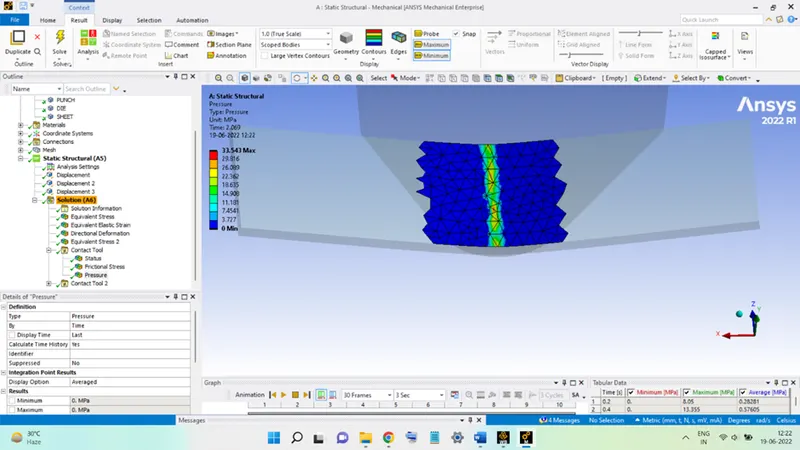
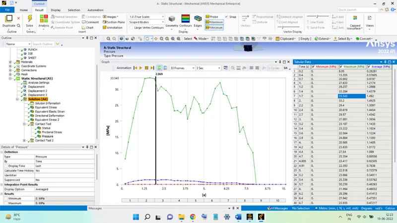
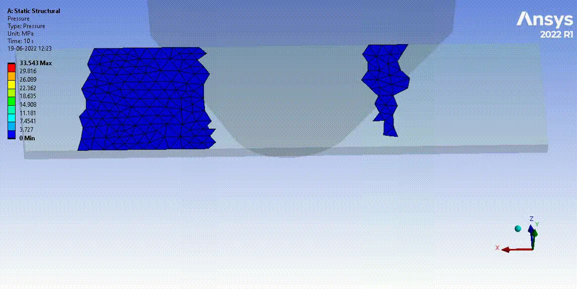
The variation of the pressure between the sheet and the die contacting surfaces is seen in the above figures. This pressure attains a maximum value of 33.543 MPa.
Contact Status between Die and Sheet:
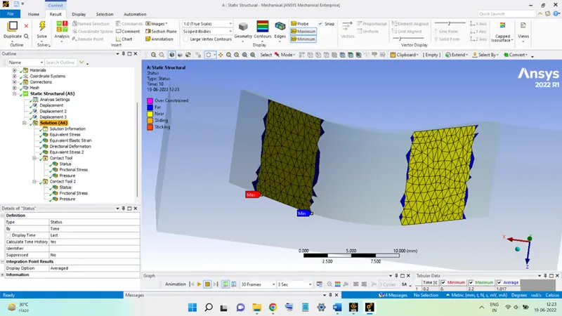
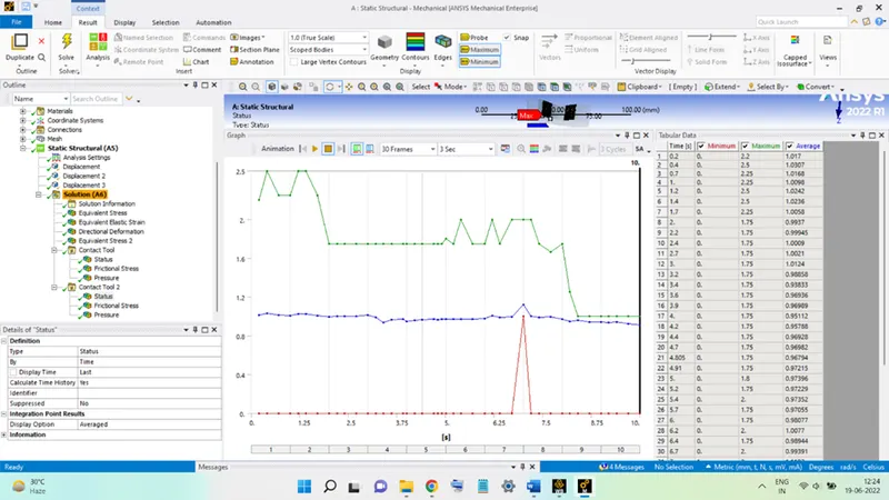
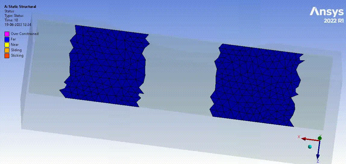
The behaviour of the contacting surfaces of the Sheet and the Die during the bending action can be seen in the above figures.
Frictional Stress between Die and Sheet:
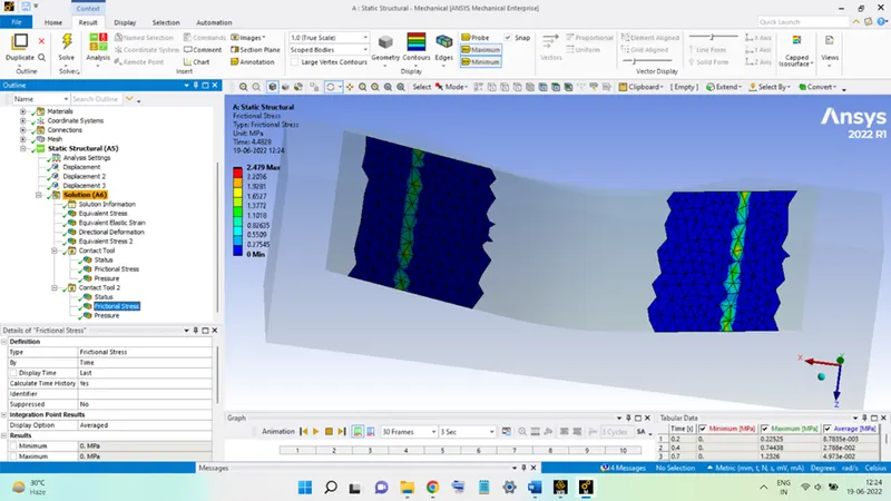
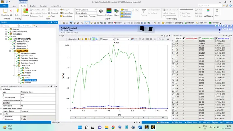
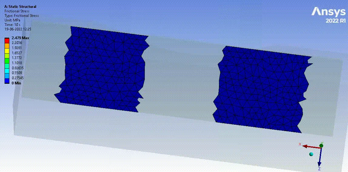
The frictional stresses present between the Sheet ad the Die are shown in the above figures, it reaches a maximum value of 2.479 MPa during the bending operation.
Pressure between Die and Sheet:
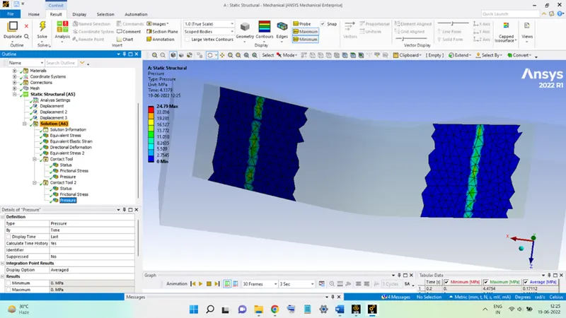
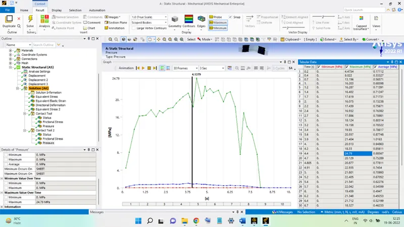
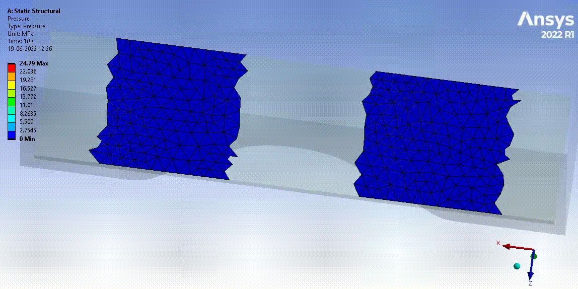
The variation of the pressure between the sheet and the die contacting surfaces is seen in the above figures. This pressure attains a maximum value of 24.79 MPa.
CASE 3: SHEET METAL IS MADE OF MAGNESIUM ALLOY NL:
Stress:
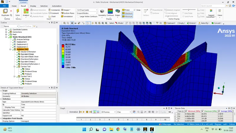
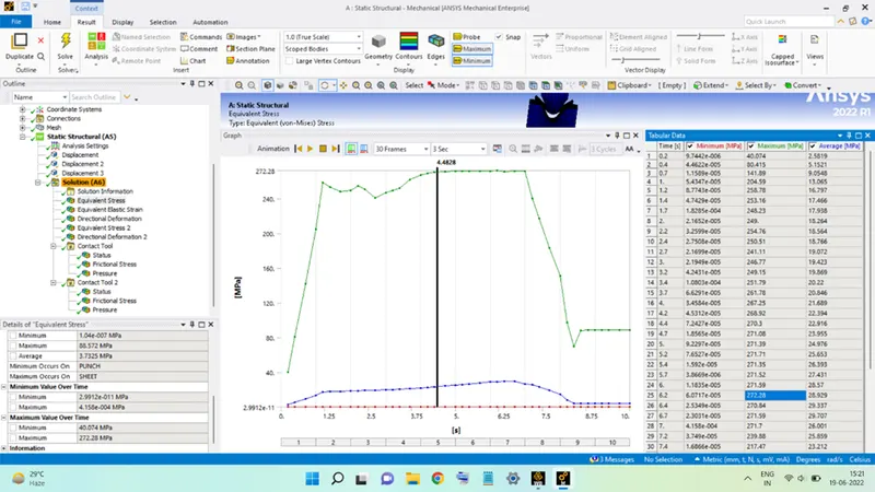
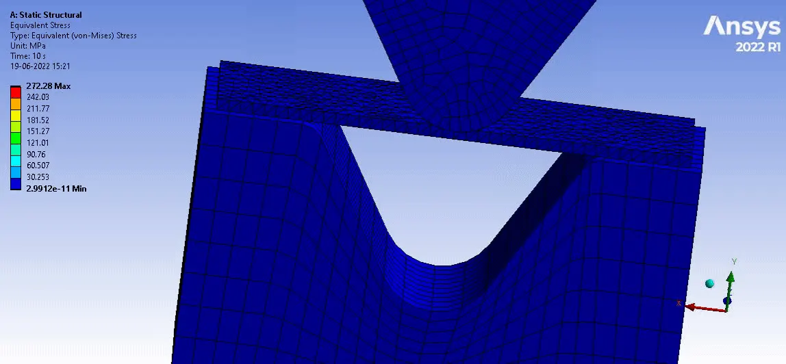
The maximum stress developed, as seen from the figure, is equal to 272.28 MPa.
Strain:
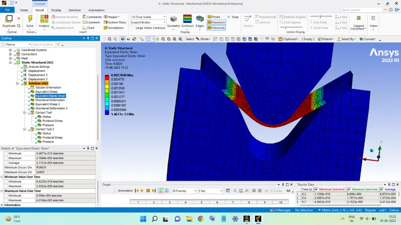
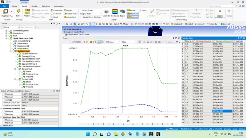
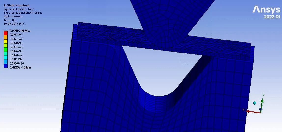
The variation of the Von-Mises strains developed throughout the bending action in the setup can be seen above. The maximum value reached is 6.0746 x 10⁻³.
Deformation in Y-Direction:
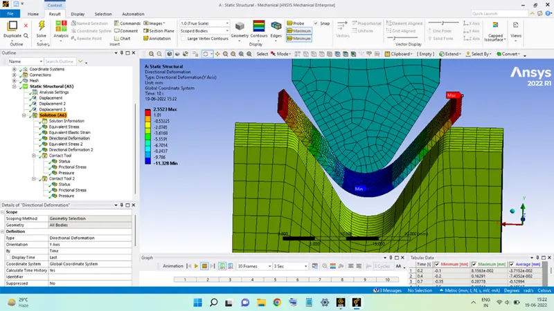
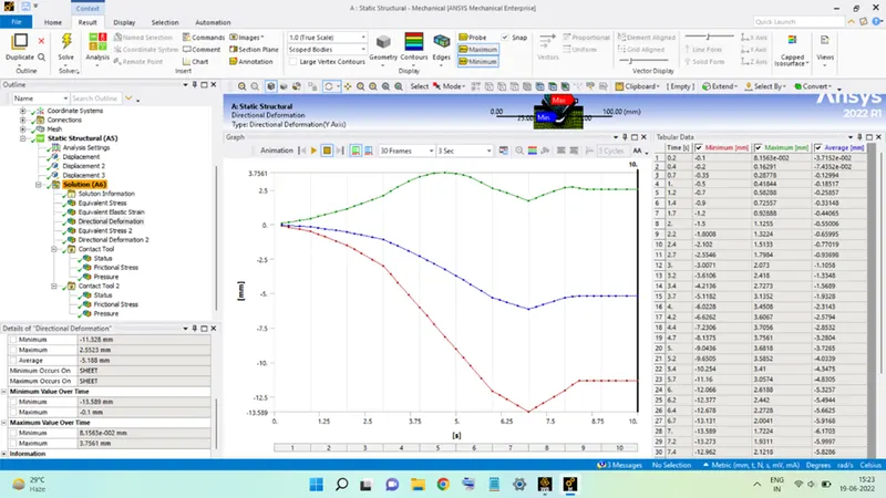
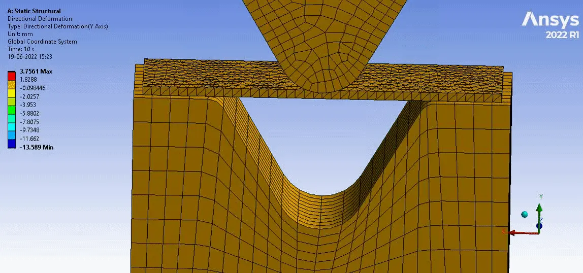
The deformation along the Y-direction is shown in the figures above.
Stress in Sheet:
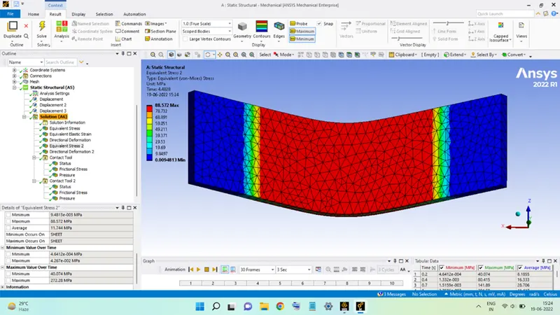
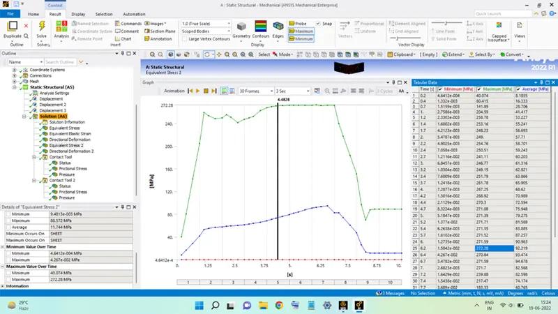
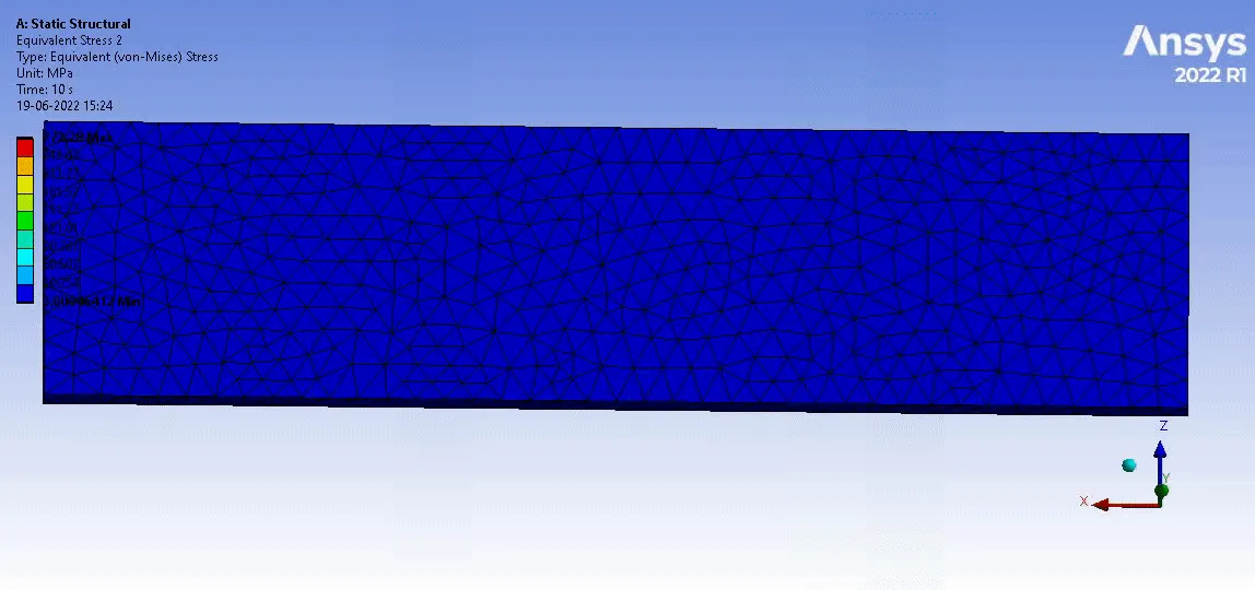
The above figures show the distribution and variation of the stress in the Sheet metal during the bending is carried out. The maximum value reached during the process is seen to be 272.28 MPa.
Contact Status between Punch and Sheet:
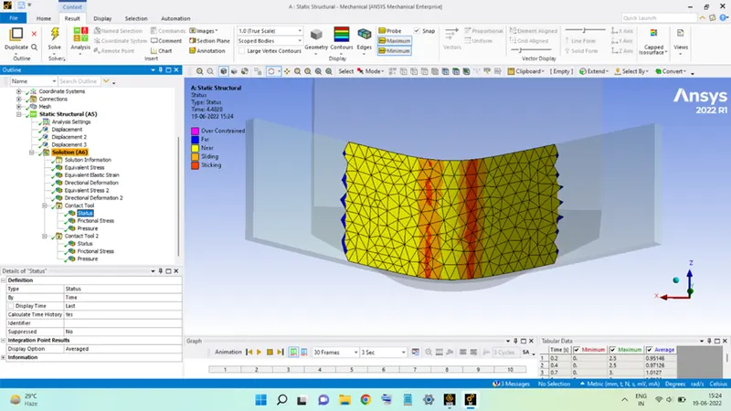
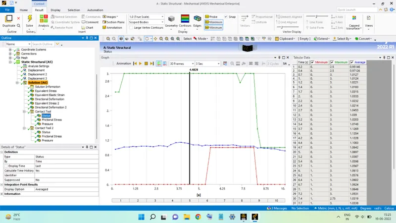
The behaviour of the contacting surfaces of the Sheet and the Die during the bending action can be seen in the above figures.
Frictional Stress between Punch and Sheet:
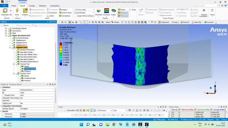
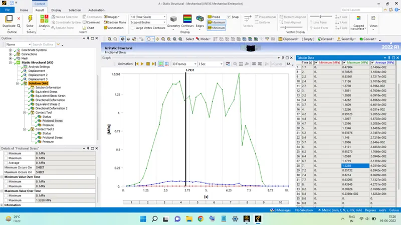
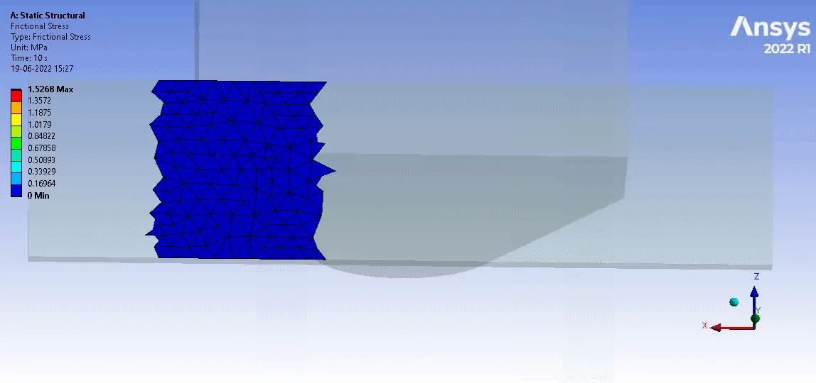
The frictional stresses present between the Sheet and the Die are shown in the above figures, it reaches a maximum value of 1.5268 MPa during the bending operation.
Pressure between Punch and Sheet:
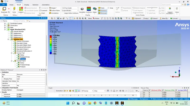
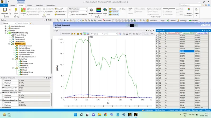
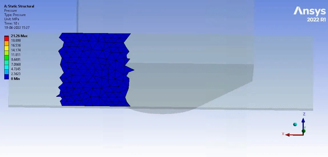
The variation of the pressure between the sheet and the die contacting surfaces is seen in the above figures. This pressure attains a maximum value of 21.26 MPa.
Contact Status between Die and Sheet:
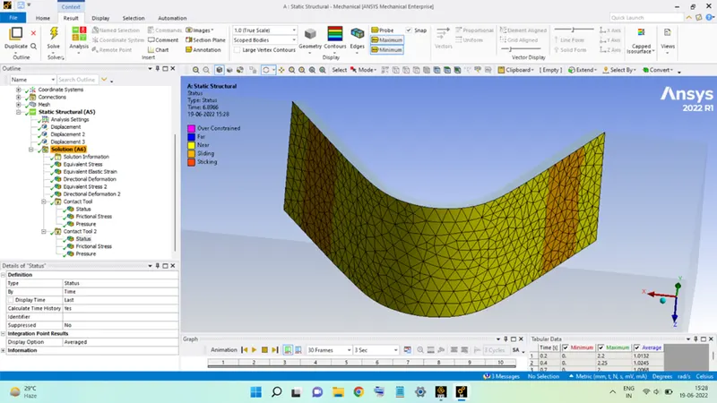
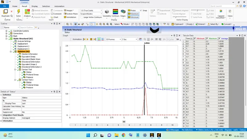
The behaviour of the contacting surfaces of the Sheet and the Die during the bending action can be seen in the above figures.
Frictional Stress between Die and Sheet:
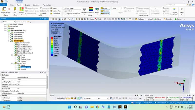
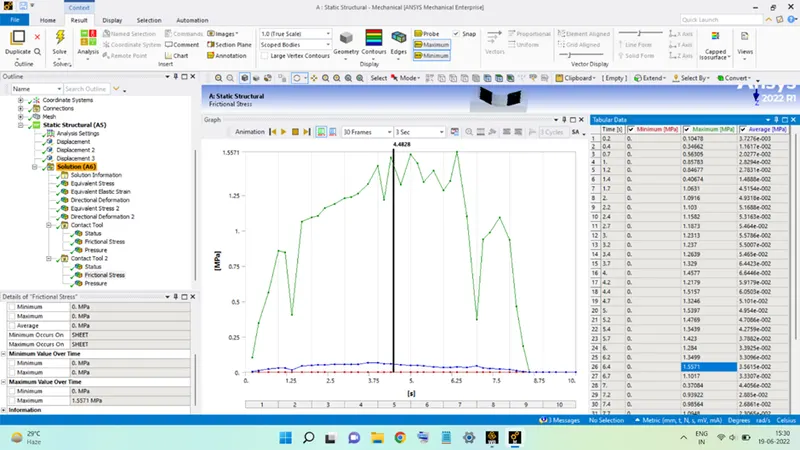
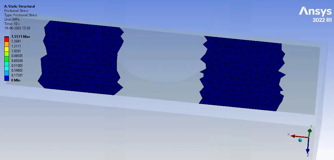
The frictional stresses present between the Sheet and the Die are shown in the above figures, it reaches a maximum value of 1.5571 MPa during the bending operation.
Pressure between Die and Sheet:
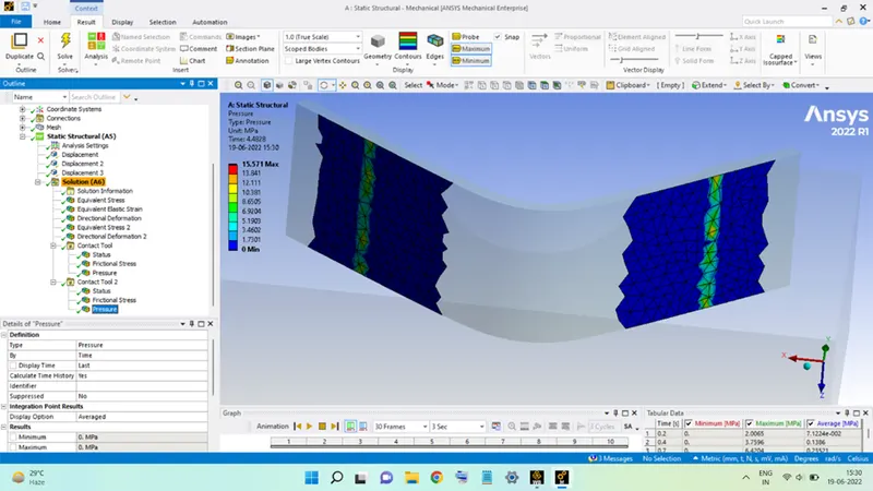
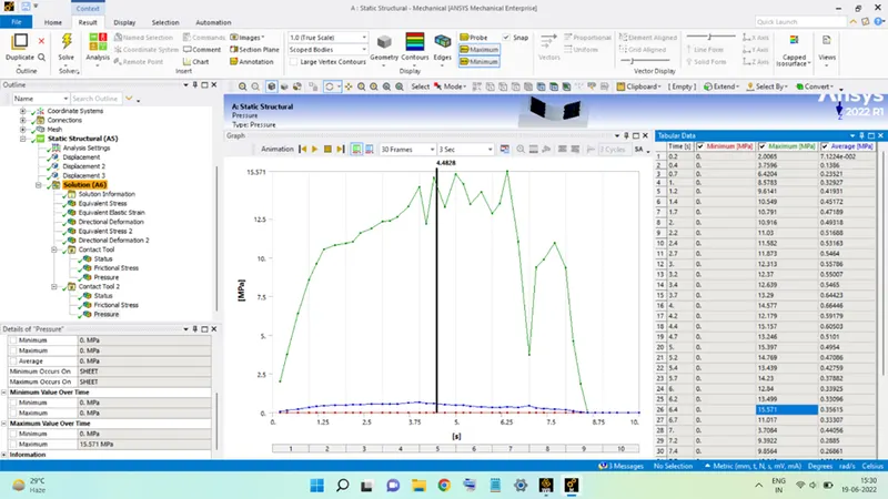
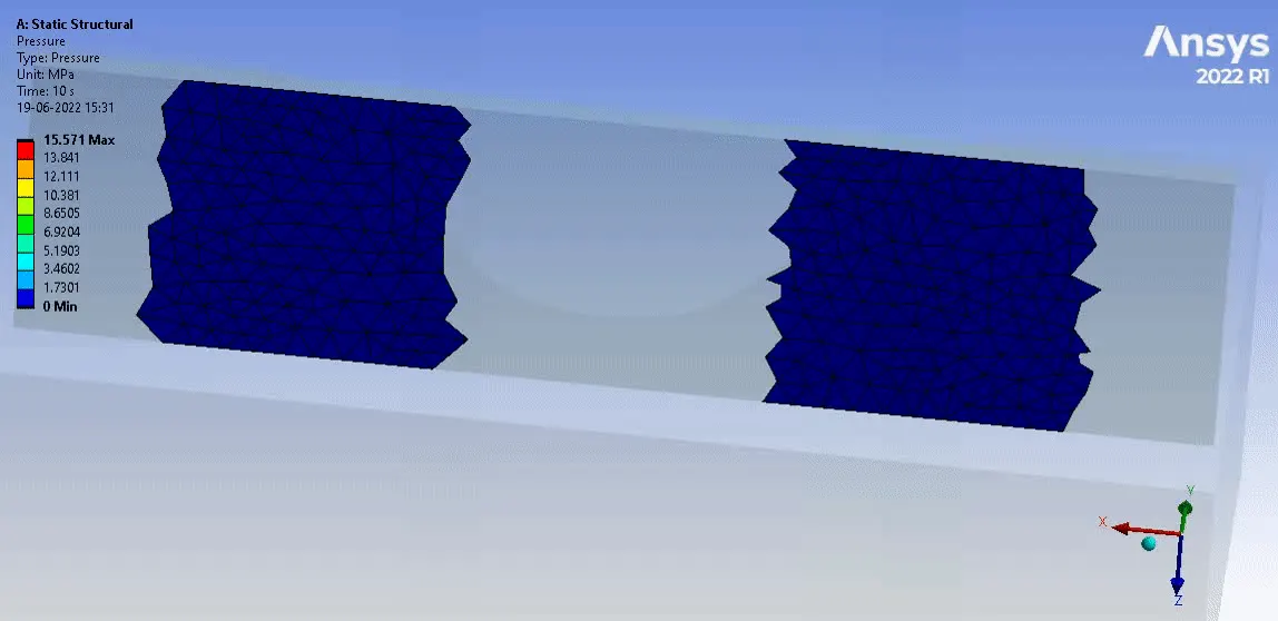
The variation of the pressure between the sheet and the die contacting surfaces is seen in the above figures. This pressure attains a maximum value of 15.571 MPa.
CASE 2: Take SHEET metal as Aluminium Alloy 1199 and change the Coefficient of Friction to 0.19 at the contacting surfaces and perform the analysis.
Stress:
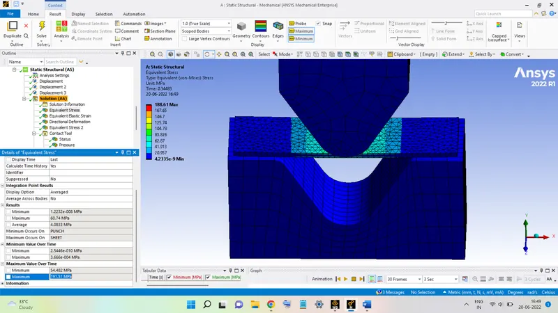
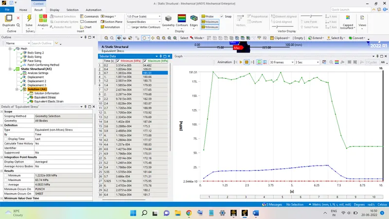
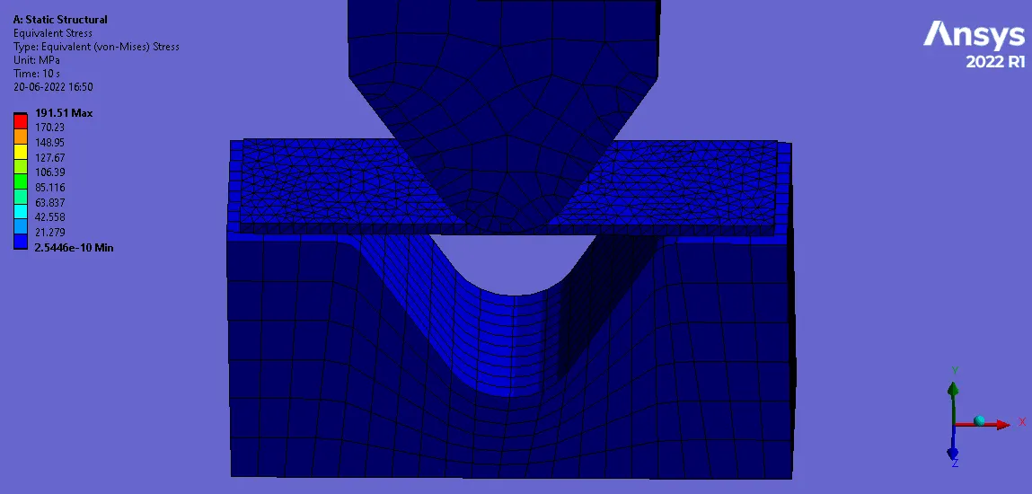
The maximum stress developed, as seen in the figure, is equal to 191.11 MPa.
Strain:
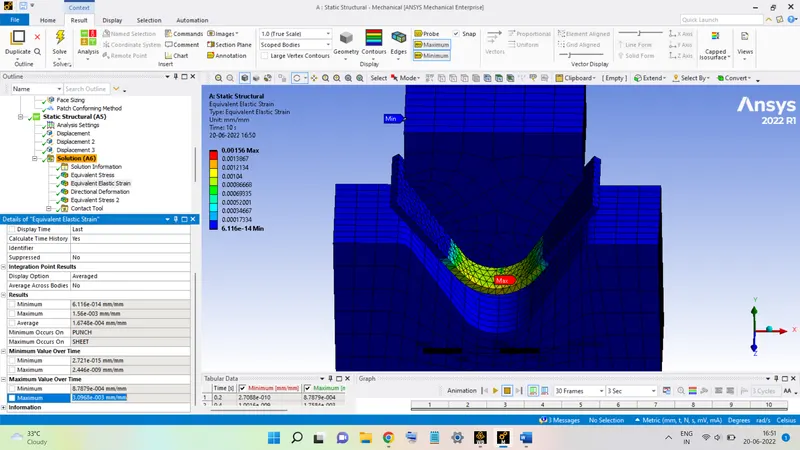
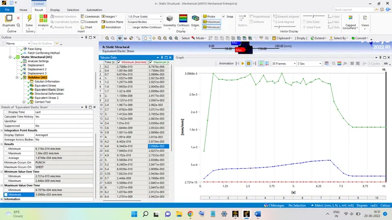
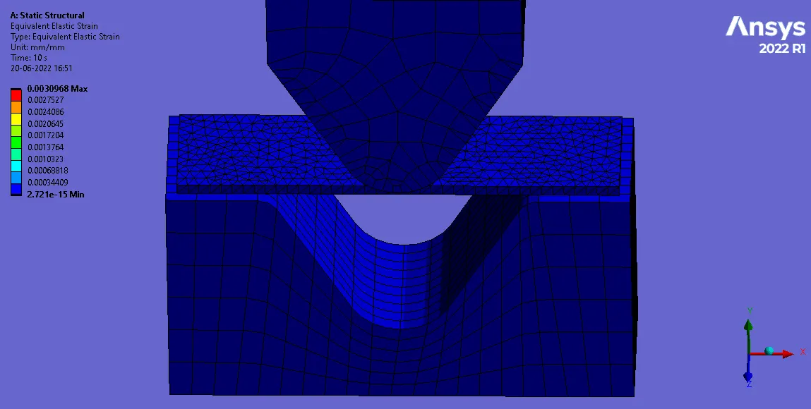
The variation of the Von-Mises strains developed throughout the bending action in the setup can be seen above. The maximum value reached is 3.0834 x 10⁻³.
Deformation in Y-Direction:
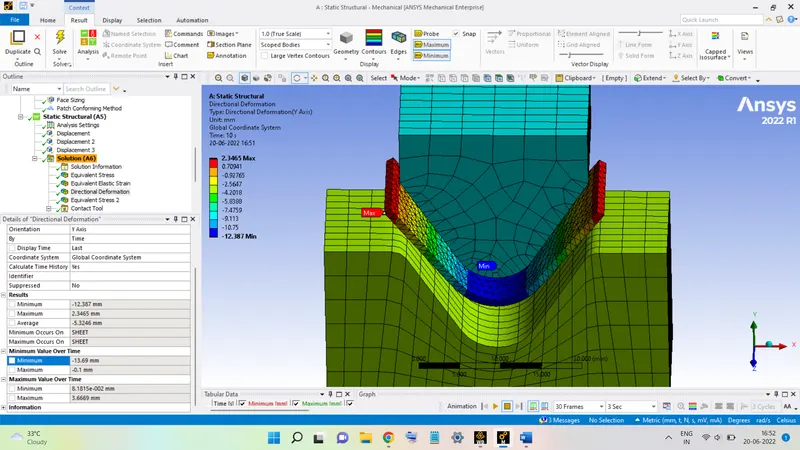
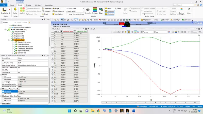
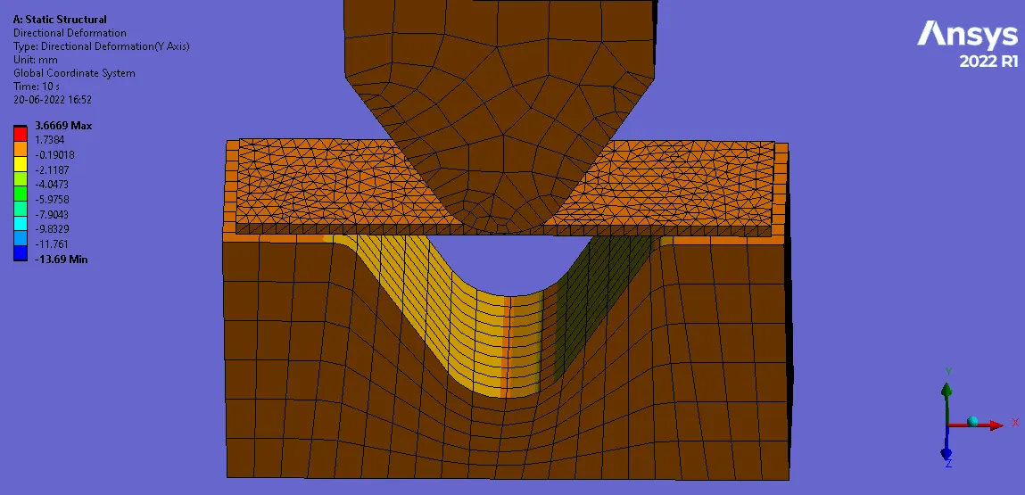
The deformation along the Y-direction is shown in the figures above.
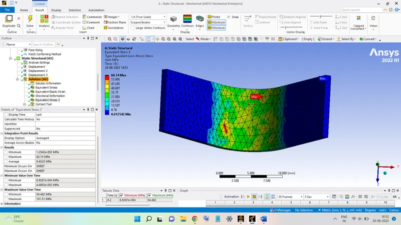
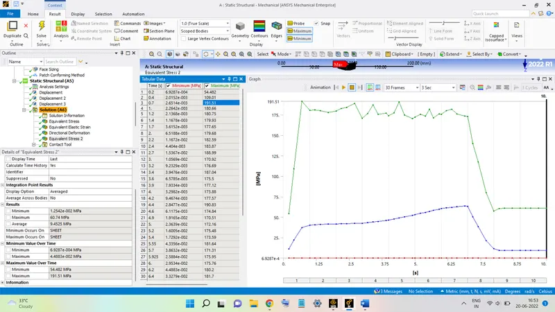
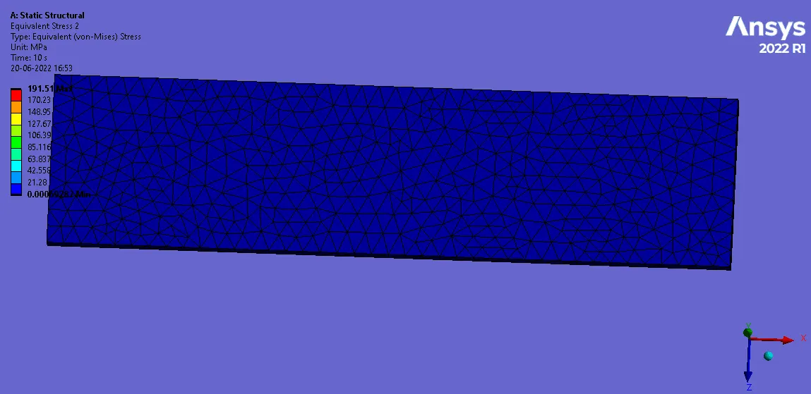
Stress in SHEET:
The below figures show the distribution and variation of the stress in the Sheet metal during the bending is carried out. The maximum value reached during the process is seen to be 191.11 MPa.
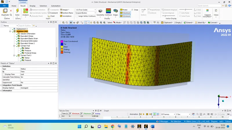
Contact Status between Punch and Sheet:
The behaviour of the contacting surfaces of the Sheet and the Die during the bending action can be seen in the figures below:
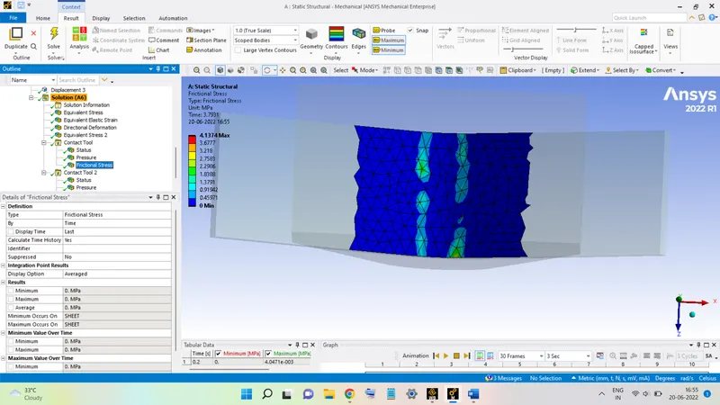
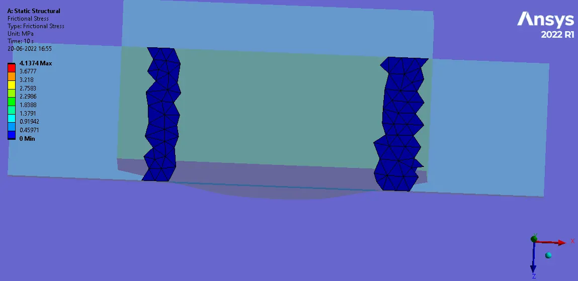
Frictional Stress between Punch and Sheet:
The frictional stresses present between the Sheet and the Die are shown below, it reaches a maximum value of 4.1374 MPa during the bending operation.
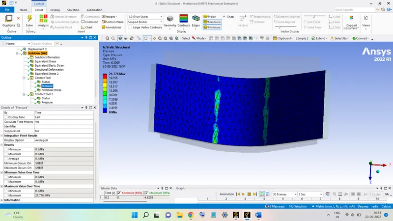
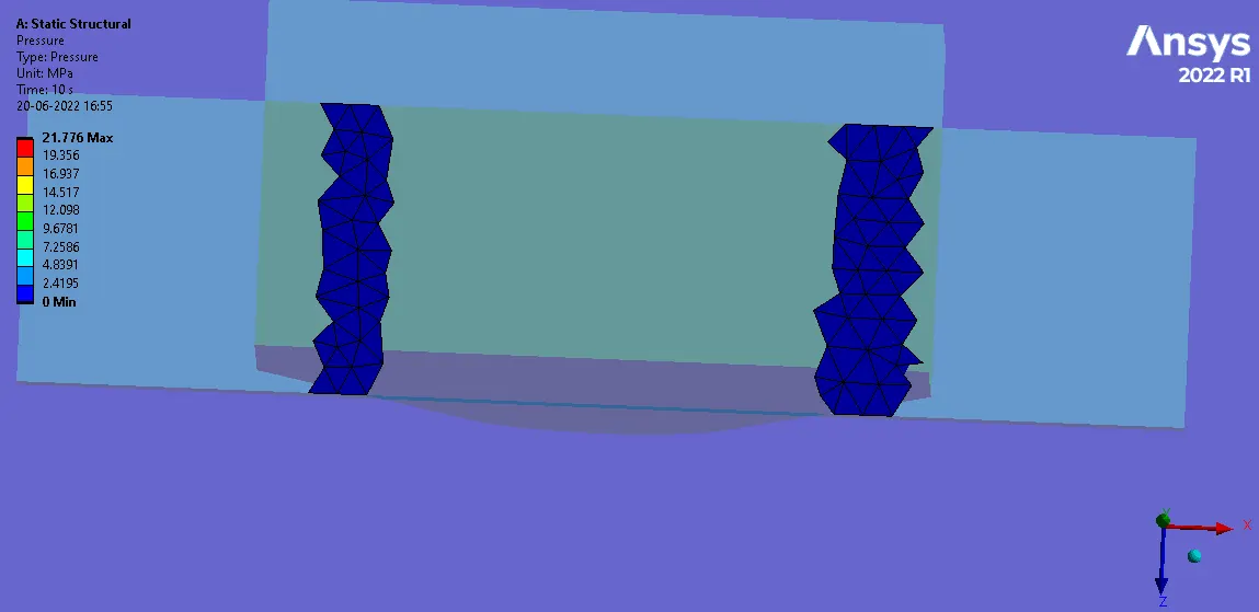
Pressure between Punch and Sheet:
The variation of the pressure between the sheet and the die contacting surfaces is seen in the figures below. This pressure attains a maximum value of 21.776 MPa.
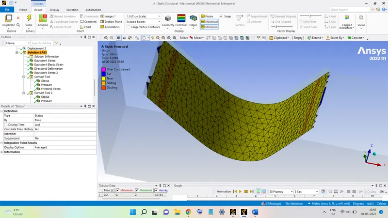
Contact Status between Die and Sheet:
The behaviour of the contacting surfaces of the Sheet and the Die during the bending action can be seen in the figures below:
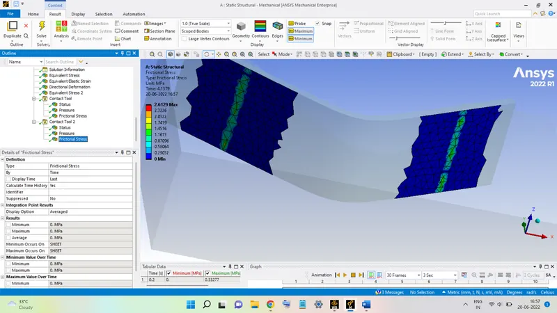
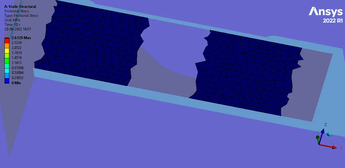
Frictional Stress between Die and Sheet:
The frictional stresses present between the Sheet and the Die are shown below, it reaches a maximum value of 2.6129 MPa during the bending operation.
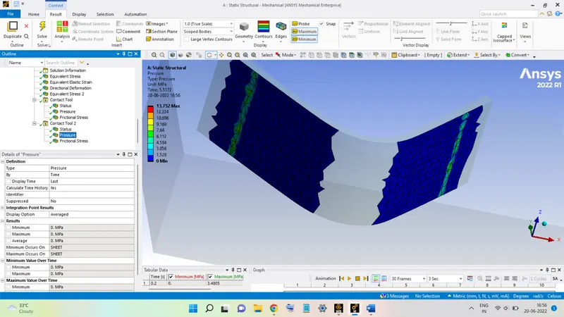
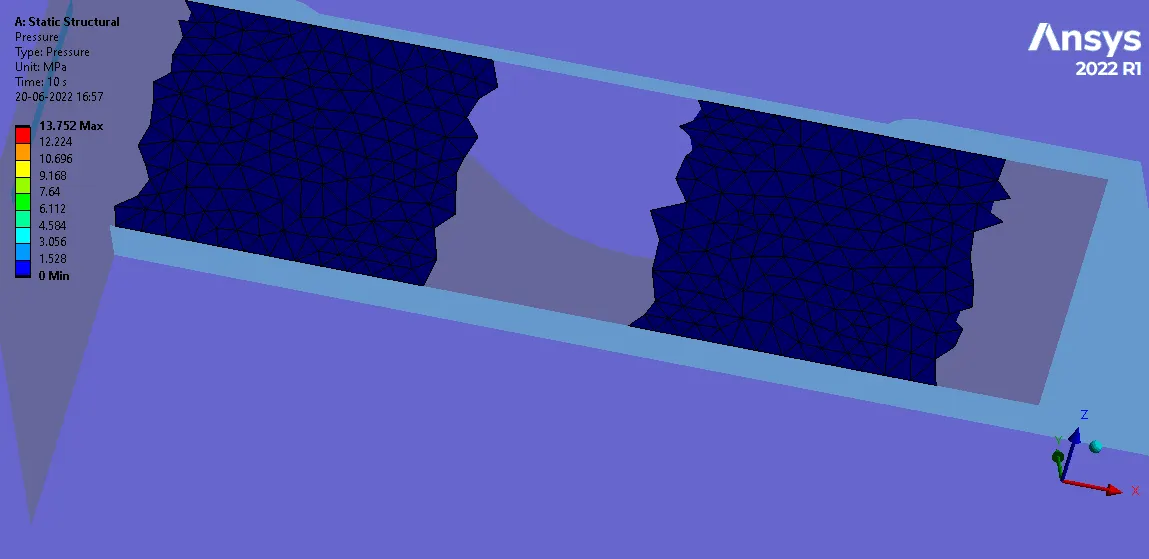
Pressure between Die and Sheet:
The variation of the pressure between the sheet and the die contacting surfaces is seen in the figures below. This pressure attains a maximum value of 13.752 MPa.
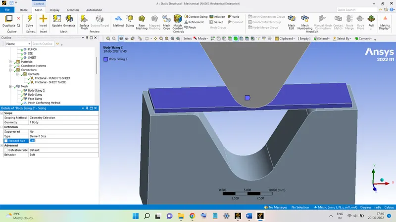
CASE 3: Refine the mesh of the SHEET such that the academic limit is not exceeded and then perform the analysis taking Aluminium Alloy 1199 as the SHEET metal.
The Element Size of the SHET is reduced to 0.68 mm, the number of nodes and elements are below the academic limit.
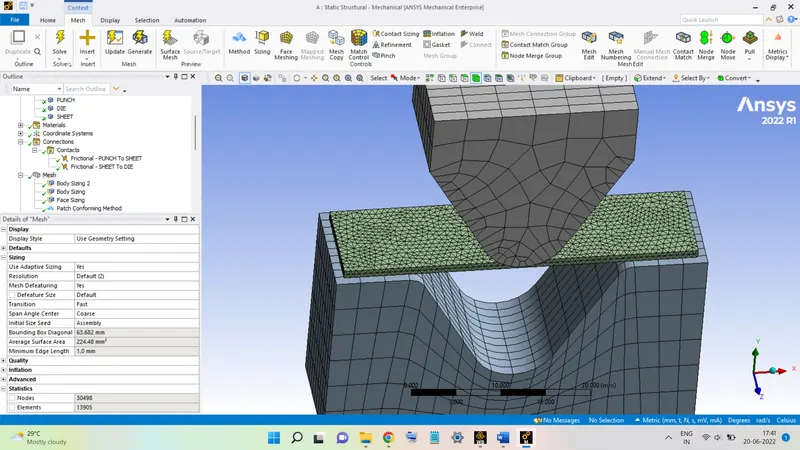
The sheet is taken to be of the aluminium alloy as shown below:
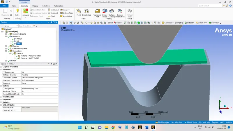
The results for this case are listed below:
Stress:
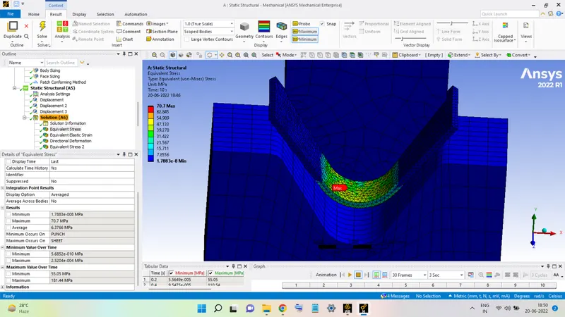
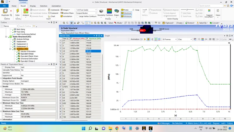
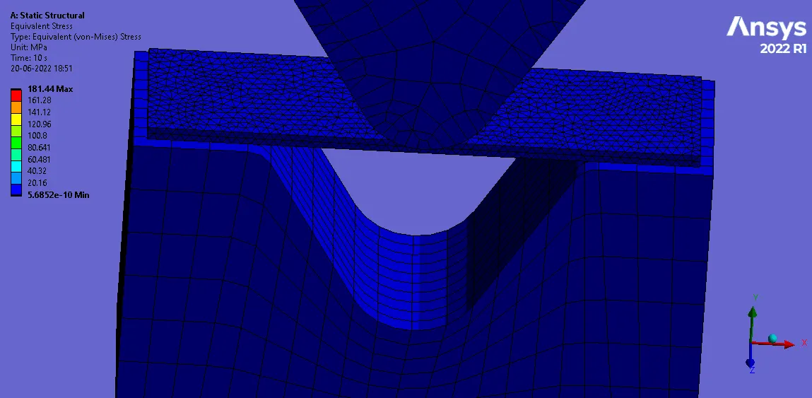
The variation of the stress in the setup is shown in the figure above. The maximum value of stress is equal to 181.44 MPa.
Strain:
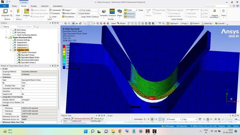
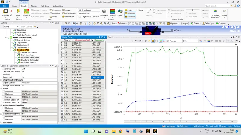
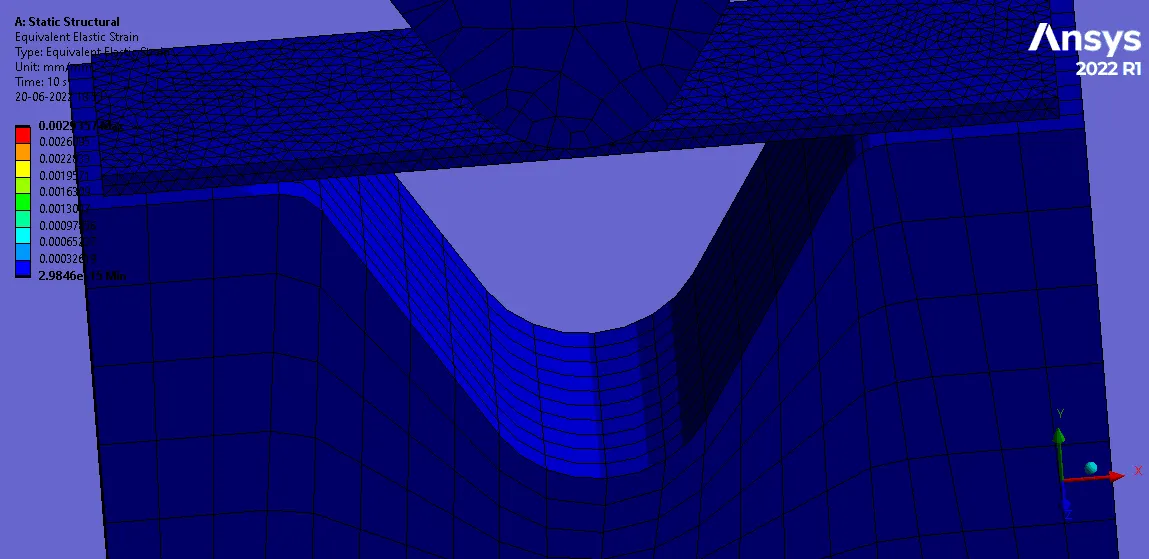
The variation of the strain in the setup is shown in the figure above. The maximum value is equal to 2.9357 x 10⁻³
Deformation in Y-Direction:
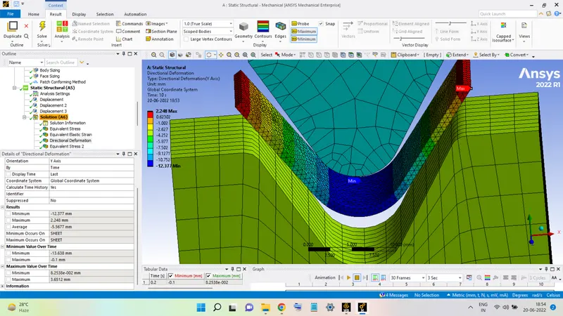
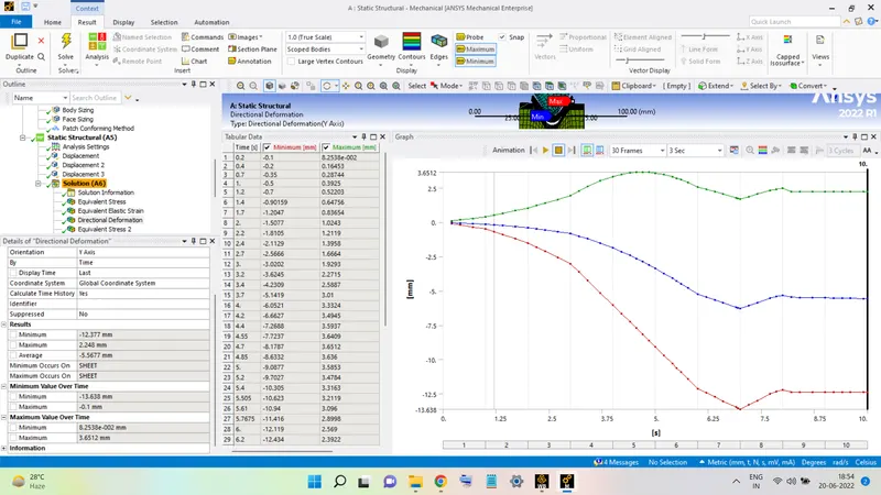
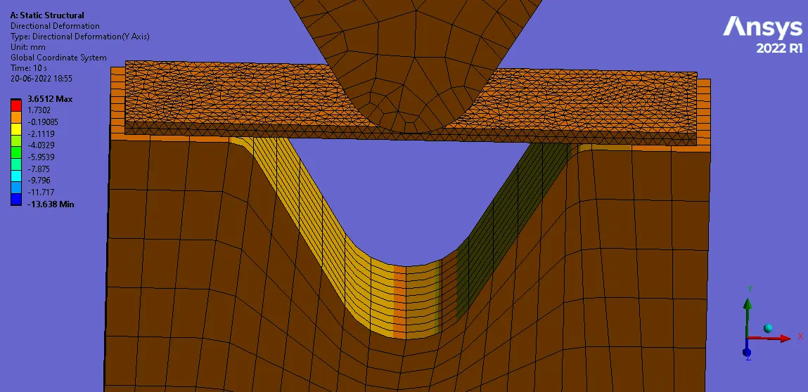
The maximum deformation in the negative Y-direction is equal to -13.638.
Stress in SHEET:
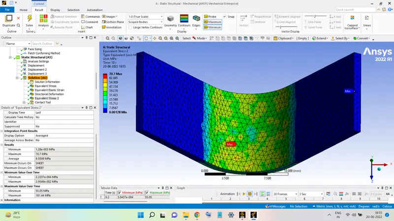
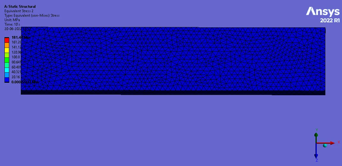
Comparison:
|
|
MATERIAL
|
Max. Equivalent Stress (MPa) |
Equivalent Strain |
Deformation in Y-direction (mm) |
|
CASE 1 Coefficient of Friction = 0.1 |
ALUMINIUM ALLOY 1199 |
191.11 |
3.0834 x 10⁻³ |
-13.763 |
|
COPPER ALLOY NL |
382.76 |
3.4983 x 10⁻³ |
-13.615 |
|
|
MAGNESIUM ALLOY NL |
272.28 |
6.0746 x 10⁻³ |
-13.589 |
|
|
CASE 2 Coefficient of Friction = 0.19 |
ALUMINIUM ALLOY 1199 |
191.51 |
3.0968 x 10⁻³ |
-13.69 |
|
CASE 3 Change of Element Size |
ELEMENT SIZE = 1 mm |
191.11 |
3.0834 x 10⁻³ |
-13.763 |
|
ELEMENT SIZE = 0.68 mm |
181.44 |
2.9357 x 10⁻³ |
-13.638 |
All the results for each case are listed in the table given above. On comparing these results, it can be said that:
1. the Copper Alloy NL, since it endured the maximum equivalent stress, required the maximum force in order to get bent by the punch. Followed by Magnesium Alloy NL and the Alloy with the least required force out of the three is Aluminium Alloy 1199.
2. The strain developed during the bending operation was seen to be maximum for the Magnesium Alloy followed by Copper Alloy and Aluminium Alloy with the least of the three.
3. The deformation for all materials was seen to be nearly the same, just slightly more than the amount of displacement given to the Punch. However, Aluminium Alloy did have the highest values for both the Element Sizes.
4. Changing the Friction Coefficient did not have much impact on the listed parameters and since the Grid Dependency Test is not done for any of the materials so it cannot be, conclusively, said about it. however, from the results provided it can be said that the friction coefficient did not have much impact.
5. The results of analysis after the refining of the mesh size within the academic limit show decreased value of the maximum stress produced during the bending of the Aluminium Alloy. The stress value is lower than obtained for other mesh parameter analyses done for aluminum. So from the analysis standpoint, the analysis with a 0.68 mm element size is not acceptable since the results obtained are lower compared to the other similar analysis.
6. Regarding the bending process, from the above experiment it can be safely said that Aluminium Alloy 1199 is the best-suited material for the bending operation, the next pick from the three will be Magnesium Alloy and Copper Alloy is the worst pick. since it requires higher stresses for bending which can result in residual stresses and strains developed.