Week 3 Sheet metal Bending challenge
OBJECTIVE
To perform static structural analysis on sheet metal bending for different materials mentioned in the following case study,
- Case 1: The material of the sheet for analysis are i.e., i) Aluminium Alloy 1199, ii) Copper Alloy NL, iii) Magnesium Alloy NL. To find out the Equivalent stress, Equivalent elastic strain and Total Deformation in Y direction and compare the results for these sheet materials.
- Case 2: With the sheet material as Aluminium Alloy, friction coefficient is changed to 0.19 and run the analysis as mentioned in Case 1. To compare the results with that in case 1.
- Case 3: To refine the mesh on the plate such that it doesn't cross the academic limit. With Aluminium alloy as material, run the analysis as in Case 1 and compare the results.
1. THEORY
1.1 Sheet Metal Bending:
Sheet metal forming processes are used on workpieces having high ratios of surface area to thickness which often prevents the thickness of the material from being reduced to avoid necking and tearing. Bends are made in sheet metal to gain rigidity and produce a part of desired shape to perform a particular function. The process of bending is commonly used to produce structural stampings such as braces, brackets, supports, hinges, angles, and channels. Bending in several directions can produce parts that otherwise would require a drawing operation. Although usually done to a 90° angle, other angles are sometimes produced by bending. The terminology for straight bending or angle bending is illustrated in Figure 1.1.1.
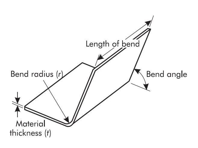
Fig. 1.1.1 Terminology for straight bending or angle bending.
A bend is achieved by stressing the metal beyond its yield strength, but not exceeding its maximum tensile strength. In bending, a unique distortion takes place as the external surface is stretched and the internal surface compressed.
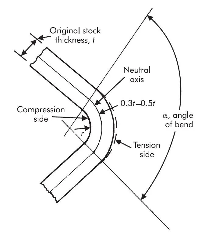
Fig. 1.1.2 Metal Bending.
As illustrated in Figure 1.1.2, the neutral axis of the bend is the location inside the material where there is neither tension nor compression. For thin materials, the neutral axis is assumed to be in the middle of the bend; but for thicker materials, it is located approximately 30% of the material thickness from the inside of the bend.
Bending is primarily done on press brakes, though stamping dies can be used. This equipment may be mechanically or hydraulically operated. similarly, to other metal-forming operations. There are two types of press brake bending operations: air bending and bottom bending as shown in Figure 1.1.3.
Fig. 1.1.3 Basic bending methods.
Air bending refers to bending operations performed in V-dies in which the punch does not bottom, resulting in low force requirements. In bottom bending, the work is completely pressed into the female die and the internal radius is accurately formed. Thus, consistently accurate flange sizes are possible. Due to the higher force required, bottom bending has a limitation with respect to maximum work thickness.
1.2 Process Parameters:
Some common bending process parameters include: the workpiece material and thickness, bend radius, and springback. The minimum bend radius is the smallest radius that can be formed without part cracking. It is a parameter that is specific to material ductility and material thickness. In general, the minimum ratio of the bend radius to material thickness increases as ductility decreases. In other words, less ductile materials require a larger bend radius or thinner material. Important material parameters are the quality of the sheared edge of the sheet metal prior to forming, the capability of the sheet to stretch uniformly, the material’s resistance to thinning, its normal and planar anisotropy, its grain size, and its yield-point elongation.
In bending, springback relates to the elastic behavior of the material. While the material is generally undergoing plastic deformation, this is not occurring throughout the entire bend. Therefore, the material will attempt to return or spring back to its original form. Springback can be predicted to a limited extent, which in typical sheet materials is in the range of 1–4°. Springback can be compensated for by overbending or bottoming. Over-bending bends the material beyond the desired shape, allowing it to spring back to the desired shape. Bottoming involves plastic deformation at the root of the bend during the bending process. Plastic deformation at the root prevents springback.
2. ANALYSIS SETUP
2.1 Geometry:
Fig.2.1 3D model of sheet metal bending.
The given 3D model of sheet metal bending assembly is imported into ANSYS Workbench for static structural analysis.
2.2 Material Properties:
a. Aluminum Alloy 1199. b. Copper Alloy NL.
c. Magnesium Alloy NL. d. Aluminum Alloy NL.
Fig.2.2 Material property details of sheet metal.
The following materials are considered for analysis of sheet metal bending i.e., i) Aluminium Alloy 1199, ii) Copper Alloy NL, iii) Magnesium Alloy NL.
For case-2 and case-3 analysis, the material considered for sheet metal is Aluminium Alloy NL.
Note: The analysis is carried out for each case separately. The analysis setup of sheet metal being Aluminium alloy 1199 is demonstrated.
2.3 Contact Details:
a. Contact between punch and sheet metal.
b. Contact between sheet metal and die.
Fig.2.3 Contact details of sheet metal bending.
Contact between, (a) punch (contact body) and sheet metal (target body), (b) sheet metal (contact body) and die (target body) are assigned as frictional contact with coefficient of friction μ=0.1. The behavior of contact is set as Auto asymmetric, formulation type is Augmented Lagrange and normal stiffness value is inputted as 0.1 factor. For case-2 analysis, the coefficient of friction considered is 0.19.
2.4 Meshing:
a. Body sizing of punch and die. b. Body sizing of sheet metal.
c. Face sizing of contact surfaces of punch and die. d. Patch conforming method of sheet metal.
e. Meshed model.
Fig.2.4 Meshing details of sheet metal bending model.
The element size of punch and die are set as 4 mm using body sizing option. The element size of sheet metal and contact regions of punch and die are set as 1 mm using face sizing option. Using patch conforming method, the element types of sheet metal is set as tetrahedron. The total number of nodes and elements generated are 18082 and 6394 respectively. For case-3 analysis, the element size of sheet metal and contact regions of punch and die are refined to 0.75 mm.
Note: The academic version of software has the problem size limit of 128k nodes or elements.
2.5 Boundary Conditions:
2.5.1 Analysis settings:
Fig.2.5.1 Analysis settings.
In the analysis settings the number of steps considered is 10. The solver type chosen is direct and with large deflection set to ‘On’. Under the nonlinear controls, the stabilization is constant with energy dissipation ratio being 0.1.
2.5.2 Boundary condition for sheet bending:
a. Displacement applied to top surface of punch in Y-direction.
b. Displacement constrained on the sheet metal in Z-direction.
c. Displacement applied on surface of die for disengagement in Y-direction after bending.
Fig.2.5.2 Boundary conditions for sheet bending.
The displacement applied to punch is such that the sheet metal has to bend in the form of V-shape. During bending, the lateral movement of sheet metal is constrained. After bending, in order to disengage the die, displacement is applied on the surface of die in Y-direction.
3. RESULTS AND DISCUSSIONS
3.1 Results of case-1:
3.1.1 Sheet material; Aluminum Alloy 1199.
a. Directional Deformation (Y). b. Equivalent Elastic Strain
c. Equivalent (v-m) stress. d. Equivalent (v-m) stress (Sheet).
3.1.2 Sheet material; Copper Alloy NL.
a. Directional Deformation (Y). b. Equivalent Elastic Strain
c. Equivalent (v-m) stress. d. Equivalent (v-m) stress (Sheet).
3.1.3 Sheet material; Magnesium Alloy NL.
a. Directional Deformation (Y). b. Equivalent Elastic Strain
c. Equivalent (v-m) stress. d. Equivalent (v-m) stress (Sheet).
3.2 Results of case-2: Sheet material; Aluminum Alloy NL (µ=0.19).
a. Directional Deformation (Y). b. Equivalent Elastic Strain
c. Equivalent (v-m) stress. d. Equivalent (v-m) stress (Sheet).
3.3 Results of case-3: Sheet material; Aluminum Alloy NL (Mesh refined).
a. Directional Deformation (Y). b. Equivalent Elastic Strain
c. Equivalent (v-m) stress. d. Equivalent (v-m) stress (Sheet).
3.4 Comparison of Results:
The results of maximum and minimum values of Directional Deformation, Equivalent Elastic Strain and Equivalent (v-m) Stress are tabulated as shown below.
| Results | Case-1: Coeff. of friction=0.1, Mesh size = 1mm |
Case-2: Coeff. of friction=0.19 |
Case-3: Mesh size=0.75mm |
|||
| Al Alloy 1199 | Cu Alloy NL | Mg Alloy NL | Al Alloy NL | Al Alloy NL | ||
| Directional Deformation, [mm] | Max. | 2.0528 | 5.3643 | 1.2157 | 2.7172 | 2.53 |
| Min. | -12.715 | -10.013 | -12.679 | -11.43 | -11.574 | |
| Equivalent Elastic Strain | Max. | 1.2327 | 1.101 | 0.87236 | 0.44589 | 1.3013 |
| Min. | 1.2984E-13 | 7.1098E-13 | 8.3813E-13 | 1.7405E-12 | 1.3711E-12 | |
| Equivalent (v-m) Stress, [Mpa] | Max. | 2.4628E+05 | 2.2000E+05 | 1.7434E+05 | 89146 | 2.6009E+05 |
| Min. | 2.5964E-08 | 1.3839E-07 | 1.6763E-07 | 3.4809E-07 | 2.7422E-07 | |
| Equivalent (v-m) Stress (Sheet metal), [Mpa] | Max. | 59.632 | 117.9 | 117.4 | 116.01 | 235.11 |
| Min. | 0.0035167 | 0.014855 | 0.12763 | 0.014188 | 0.003129 | |
For case-1; from the table, it is observed that the maximum deformation occurring in bending of copper alloy NL sheet metal is highest i.e., 5.3643 mm whereas, for magnesium alloy NL sheet metal is lowest i.e., 1.2157 mm. The maximum equivalent elastic strain and v-m stress developed in bending of aluminum alloy 1199 sheet is highest i.e., 1.2327 and 2.4628E+05 MPa whereas, for magnesium alloy NL sheet metal is lowest i.e., 0.87236 and 1.7405E+05 respectively. The maximum v-m stress developed in the sheet metal of aluminum alloy 1199 is 59.632 MPa, which is lowest compared to other two cases of sheet metal.
For case-2; from the table, it is observed that as the coefficient of friction is increased to 0.19 for aluminum alloy NL sheet material, the maximum deformation occurred is 2.7172 mm and maximum v-m stress developed in sheet metal is 116.01 MPa which is more compared to aluminum alloy 1199, but maximum equivalent elastic strain and v-m stress developed in sheet metal bending is less compared to aluminum alloy 1199.
For case-3; from the table, it is observed that as the mesh size for sheet metal is refined to 0.75 mm the outcome of the results is showing minor variation compared to case-1 and case-2, due to better approximation of result, because of mesh refinement.
3.5. Animation of Results:
Case-1: (i) Sheet material; Aluminum Alloy 1199.
a. Directional Deformation (Y). b. Equivalent Elastic Strain
c. Equivalent (v-m) stress. d. Equivalent (v-m) stress (Sheet).
Case-1: (ii) Sheet material; Copper Alloy Nl.
a. Directional Deformation (Y). b. Equivalent Elastic Strain
c. Equivalent (v-m) stress. d. Equivalent (v-m) stress (Sheet).
Case-1: (iii) Sheet material; Magnesium Alloy NL.
a. Directional Deformation (Y). b. Equivalent Elastic Strain
c. Equivalent (v-m) stress. d. Equivalent (v-m) stress (Sheet).
case-2: Sheet material; Aluminum Alloy NL (µ=0.19).
a. Directional Deformation (Y). b. Equivalent Elastic Strain
c. Equivalent (v-m) stress. d. Equivalent (v-m) stress (Sheet).
case-3: Sheet material; Aluminum Alloy NL (Mesh refined).
a. Directional Deformation (Y). b. Equivalent Elastic Strain
c. Equivalent (v-m) stress. d. Equivalent (v-m) stress (Sheet).
CONCLUSION
- Static structural analysis on sheet metal bending was performed for different sheet materials mentioned in the case study.
- By comparing the results of case-1, Aluminium Alloy 1199 is exhibiting better results compared to other sheet materials due it’s ductile nature, moderate value of elastic modulus and better yield-point elongation.
- On comparing the results of case-2 with case-1, as the coefficient of friction is increased deformation and v-m stress in sheet metal is also increased marginally.
- On comparing the results of case-3 with case-1 and case-2, as the meshed is refined outcome of the results showed minor variation compared to case-1 and case-2, because of better approximation of result, due of mesh refinement.
- Because of the relatively thin materials used, springback, buckling, and wrinkling are significant problems in sheet forming. Springback is a function of the yield stress, the elastic modulus, and the ratio of bend radius to thickness. These problems can be reduced or eliminated by proper tool and die design, by minimizing the unsupported length of the sheet during processing, and by controlling the thickness of the incoming sheet and its mechanical properties.