Week 3 Sheet metal Bending challenge
Objective: Carrying out a finite element simulation for the bending of a sheet using a punch (or ram) and a die and calculating stress and strain produced on sheets of different materials and in different simulation parameters.
Modelling:
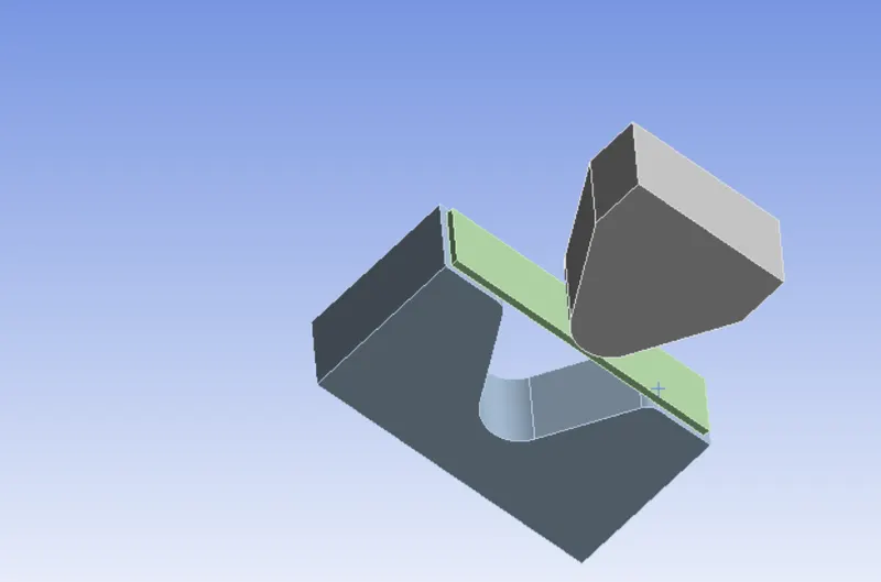
In a sheet bending process, the sheet is placed on a die, which has a valley like opening. A punch applies a force on the sheet and plastically deforms it at the point of contact till the sheet starts touching the die opening sides. The main motive of this process is the plastic deformation of the sheet and according to the material of the sheet, appropriate force needs to be applied to the sheet by the punch in order to plastically deform it, i.e. the stresses generated in the sheet due to the punch should be beyond the yield strength of the sheet material.
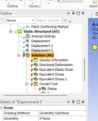
In the model, the die is kept fixed at a place and the punch has a downward motion. Here, a downward displacement to the punch is more suitable boundary condition than a load, because the displacement specification means that the punch has to travel the specified distance and thus the sheet will deform that much. The force applied to the sheet gets adjusted on the basis of the amount of deformation the sheet has to go through for the specified punch movement, thus meaning that the stresses generated in the sheet will be enough for the plastic deformation (>yield strength) irrespective of the sheet material.
Material:
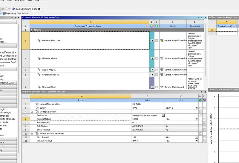
An analysis was conducted for three different materials of the sheet metal namely Aluminium Alloy 1199, copper Alloy NL, Magnesium Alloy NL Non-linear materials are considered to account for the regions of plastic deformation
Mesh
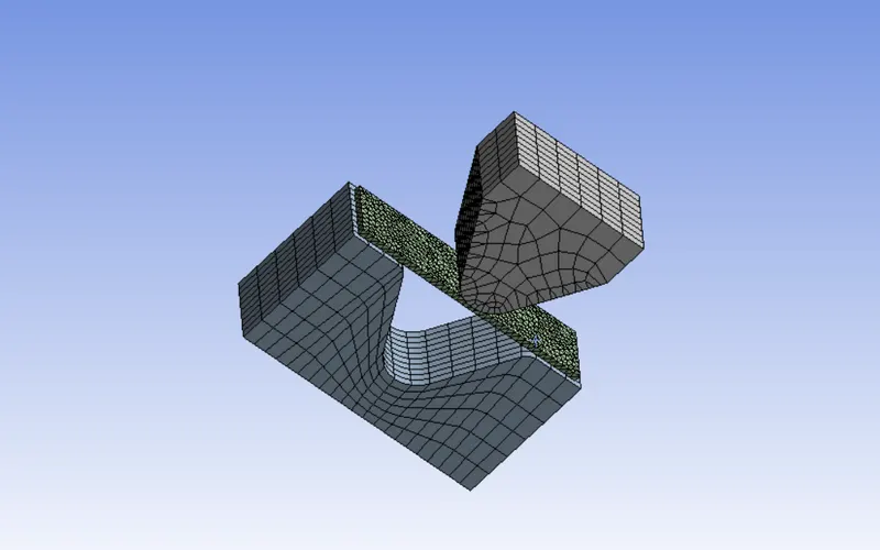
• The sheet metal and faces of punch and die which come in contact with sheet are alone meshed with an element Size of 1mm.other part are meshed with an element size of 4mm
. For case (3) - the sheet metal and the face of punch and die which come in contact with sheet are alone meshed with an element size of 1.5mm. the sheet metal element are of tetrahedrons type
Analysis settings:
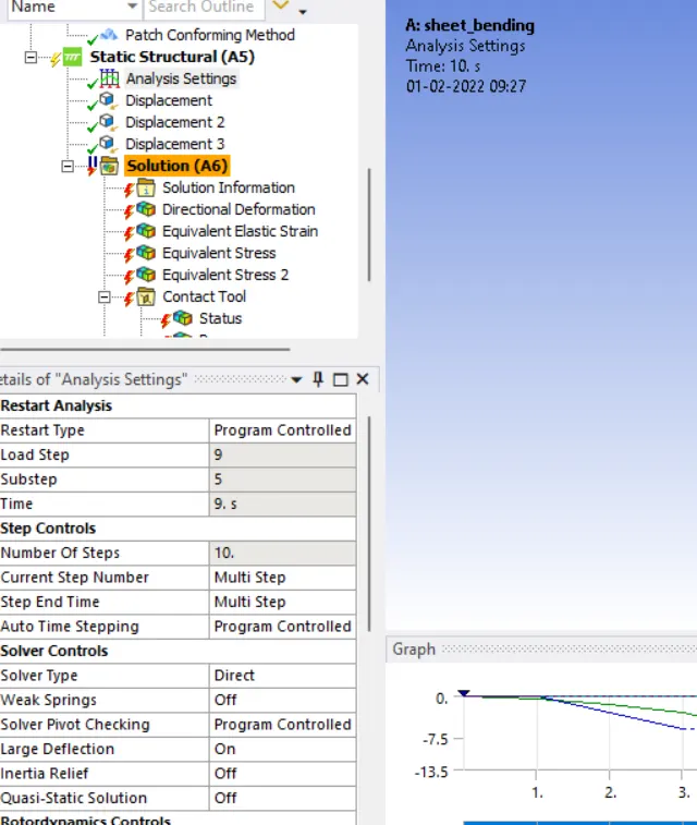
The number of loadsteps in the model are 10 and for each step, the time stepping is program controlled. The direct solver is used and since this problem includes a large amount of deformations and non-linearity, both material and geometric, large deflections has been activated and stabilization has been added, which helps in convergence of problems including large displacements by providing damping to the excessively deforming nodes. The stabilization is given by the energy dissipation ratio of the value 0.1.
Contacts:
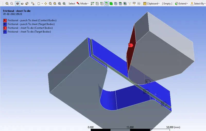
All contacts in this model have been considered frictional. For all the contacts:
Behaviour Auto-Asymmetric
Formulation: Augmented lagrange
Normal Stiffness/Contact stiffness = 0.1x(value of programmed controlled stiffness) Interface Treatment: Add offset, Ramped Effects
For the contact between the punch and the sheet, the load is transferred from the punch to the sheet, thus making the punch the contact body and the sheet the target body.
SOLUTIONS
CASE 1:
RESULTS OF ALUMINIUM ALLOY 1199
VAN STRESS
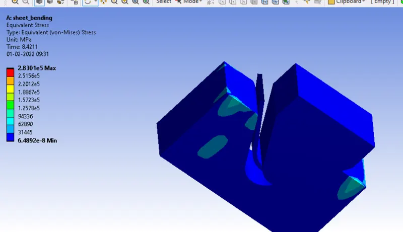
sheet stress
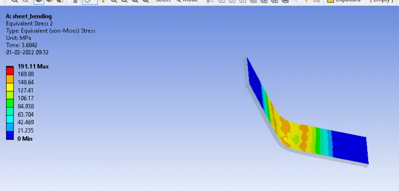
total deformation
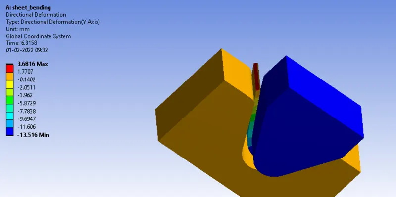
RESULT OF COPPER ALLOY NL
Stress
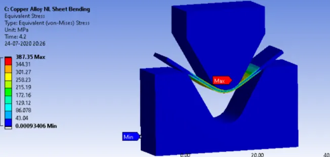
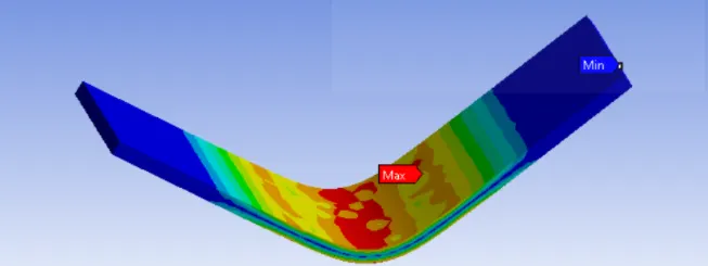
sheet stress
Diresctional deformation
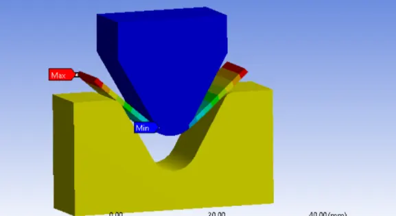
RESULTS OF MAGNESIUM ALLOY
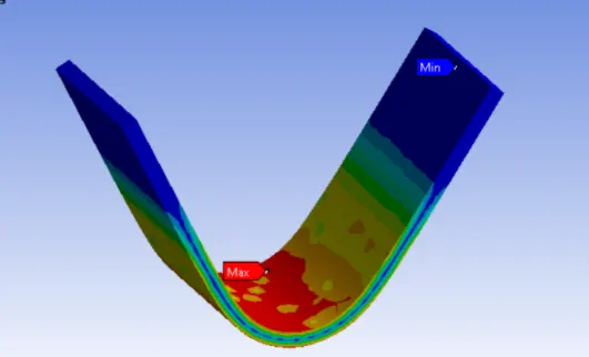
SHEET STRESS
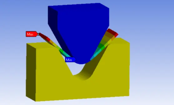
DIRECTIONAL DEFORMATION
Case 2: With the material as Aluminium Alloy, change the friction coefficient to 0.19
The frictional coefficient will have an impact on the punch force needed and therefore it is useful to keep it as low as possible. The contact tool is used to obtain the frictional stress between the two aforementioned contacts.
As the frictional coefficient increases, Equivalent stress and Equivalent strain decreases and Directional deformation increases.
Result for refined mesh element size of 0.8mm on the sheet (Case 3/DP2):
For this case the body sized mesh on the plate is refined further from element size of 1mm to 0.8mm and it is ensured that the number of nodes and elements stay below the academic limit (32k)
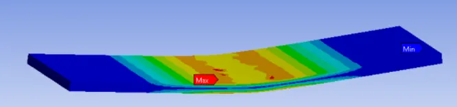
SHEET STRESS
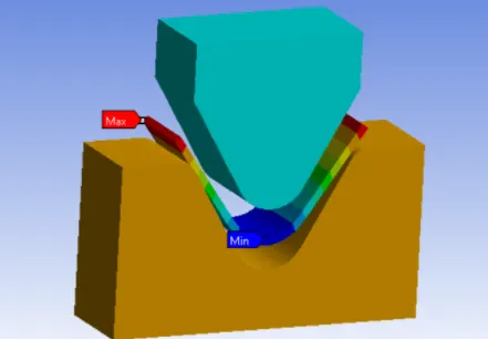
DIRECTIONAL DEFORMATION
STRAIN
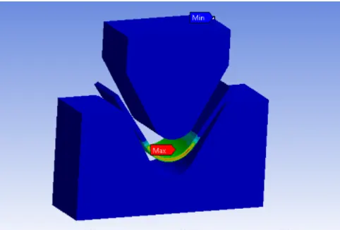
Case- 1 Among the three materials used Aluminums alloy 1199 has the least amount of stress developed
Case-2-with Aluminium alloy 1199 as material, changing the frictional coefficient from 0.1 to 0.19 doesn't affect the results.
Case-3-with Aluminium alloy 1199 as material, increasing the mesh size from 1mm to 1.5mm doesn't affect the results.