Week 3- Geometry cleanup and Mid-surfacing
CASE-1: GEOMETRIC MODELLING IN SPACE CLAIM REPORT:
Report on Operations Performed in Ansys SpaceClaim
1. Midsurfacing the Tube
Module:
SpaceClaim: Prepare: Midsurface
Description:
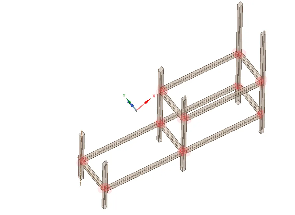
Midsurfacing is a process used to extract the mid-plane of thin-walled structures such as tubes to simplify the model for shell-based finite element analysis. This operation reduces computational complexity while maintaining accuracy in stress and deformation predictions. The midsurface extraction in SpaceClaim is performed under the Prepare tab, ensuring that the sheet body represents the tube's structural behavior correctly.
2. Extend Operations
Module:
SpaceClaim: Design: Extend
Description:
The Extend operation is used to lengthen a surface or edge to properly align with adjacent features. This ensures continuity between different parts of the geometry, avoiding gaps and inconsistencies in meshing. In SpaceClaim, this tool is found under the Design tab. It is commonly used after midsurfacing to ensure all surfaces extend and connect seamlessly, preparing the model for accurate meshing and analysis.
3. Gap Check Operation
Module:
SpaceClaim: Workbench: Gap Check
Description:
The Gap Check tool is used to identify and highlight any unintended gaps between surfaces or edges in a geometry. This is crucial in ensuring that all parts of the model are properly connected before proceeding with the simulation. In SpaceClaim, this tool is found under the Workbench tab. It helps in preventing issues related to mesh discontinuity, ensuring that forces and deformations are transferred correctly between elements.
4. Shared Topology Operation
Module:
SpaceClaim: Workbench: Sharing
Description:
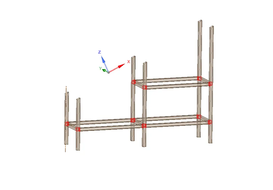
The Shared Topology operation is used to merge separate surfaces or bodies into a single connected entity. This ensures that mesh nodes at the interface between different bodies remain connected, preventing artificial discontinuities in simulation results. This operation is critical for structural and thermal analyses where load transfer needs to be continuous across different parts of the model. In SpaceClaim, this tool is located under the Workbench tab, and it is a necessary step to ensure proper contact and connectivity in the finite element model.
Conclusion:
Each of these operations plays a vital role in preparing the geometry for an accurate finite element simulation. Midsurfacing simplifies the model, extend operations ensure proper alignment, gap checking verifies connectivity, and sharing ensures correct load transfer between components. Using these tools correctly within SpaceClaim ensures an efficient and reliable simulation setup in Ansys Workbench.
CASE-2
Modal Analysis Report
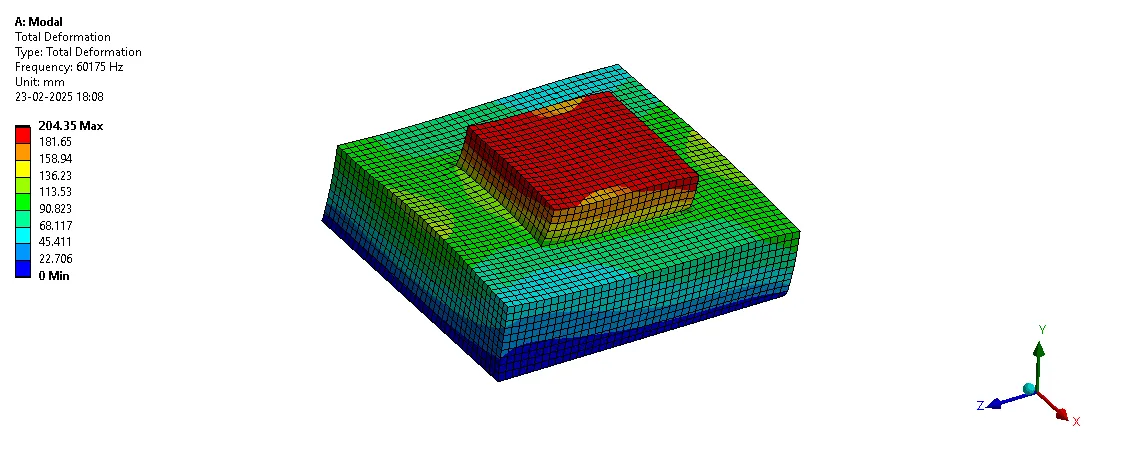
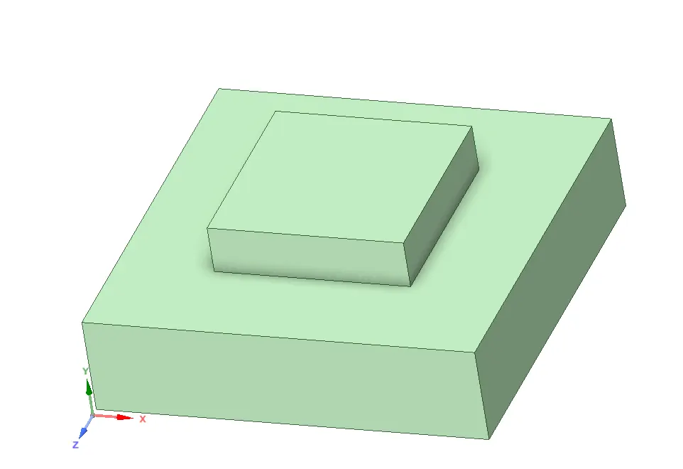
1. Introduction This report presents the modal analysis of a system consisting of two blocks, one positioned on top of the other, with shared faces. The purpose of this study is to determine the natural frequencies and deformation patterns of the system under different boundary conditions. Two cases were analyzed:
- Free-Free Analysis to check for rigid body motion.
- Modal Analysis with a fixed bottom surface to identify structural vibrational modes.
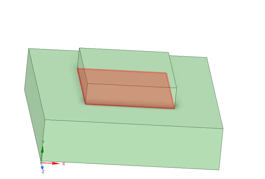
2. Geometry Modeling The geometry was created in ANSYS SpaceClaim, where two blocks were modeled with a shared interface. The following techniques were used:
- Splitting: The geometry was split to create distinct sections and ensure proper mesh connectivity.
- Sharing Faces: Shared topology was assigned to ensure a continuous and conformal mesh between the two blocks.
- Boolean Operations: Used to maintain connectivity and allow effective simulation of interactions between blocks.
3. Meshing Strategy The meshing process utilized the MultiZone method to ensure high-quality elements. The key meshing parameters include:
- Element type: Hexahedral
- Mesh refinement at the shared interface
- Global element size control to balance accuracy and computational efficiency
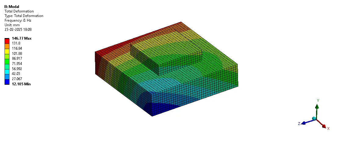
4. Modal Analysis Setup Two different modal analysis cases were performed:
- Case 1: Free-Free Analysis
- No constraints were applied to check for rigid body modes.
- This ensures that the structure behaves as expected in an unconstrained state.
- Case 2: Fixed Support at Bottom
- The bottom face was constrained to simulate a fixed boundary.
- This identifies structural natural frequencies and deformation modes.
5. Results The results of the modal analysis are summarized below:
| Mode | Frequency (Hz) |
| 1 | 60175 |
| 2 | 60175 |
| 3 | 70133 |
| 4 | 84470 |
| 5 | 84470 |
| 6 | 85944 |
| 7 | 87514 |
| 8 | 93065 |
Free-Free Modal analysis done for Rigid Body motion analysis
Fixed Free Analysis